During the past year, we implemented over 40 updates to our Wood Framing and Metal Framing BIM software for designing walls, floors, and roofs of prefabricated timber and light-gauge steel-framed buildings in Revit®.
These updates include new features, enhanced sample families, and requests made by clients that benefit many of our users. In the spirit of sharing BIM advances, we walk through over 30 of them now in the hopes that this summary will be of use to not only current users but also Revit users generally and those who may be considering making the switch over to a BIM workflow for framing design.
We’ve put a lot of work into our Wood Framing and Metal Framing BIM software over the past year to make sure it continues advancing to meet the needs of architects and structural engineers around the world. Click a topic in the list below to auto-scroll down for more about it.
By the way, we also hosted this webinar in June 2021 that goes over most of the features enumerated below.
Framing enhancements
- Separate Preassemblies for Joined Openings
- Transportation Braces
- Align Secondary Stud System with Project Base Point
- Additional control over Brace Groups
- Partial Brace Groups
- Special Layouts for Paneling, additional Splitting Options
- Minimum dimensions for framing openings
- Toggle visibility of configuration types
- Reduced number of Roof+ families but more flexible and intelligent
- New cutting technology for Roof+
- New framing direction option for Roof+
- Efficiently fixing or replacing Types in Configurations
- Better control of Top and Bottom Cripples
- Link Database configurations together
- Flexible management of Plates in connections
- Increased Split Elements functionality
- Opening Configuration by Family Type
- Reconfigure sheathing and paneling
- Create or exclude parts with Frame Wall
- Cut Plates and Siding with Additional Opening Voids
- Add a Mid-ridge stud
- More options for preassembled openings
- Add more tabs for dimensioning rules
- Auto-dimension part openings
- Use material as a text note parameter
- Placement of assembly views
- Disable analytical lines
- Framing in Groups
- Transfer Host Mark Value into Parts When Number Parts is Used
- Flip Ordinate dimensions
- Total Diagonal Dimensions
- QR/Barcode Generator added to Sort Mark Revit Tool
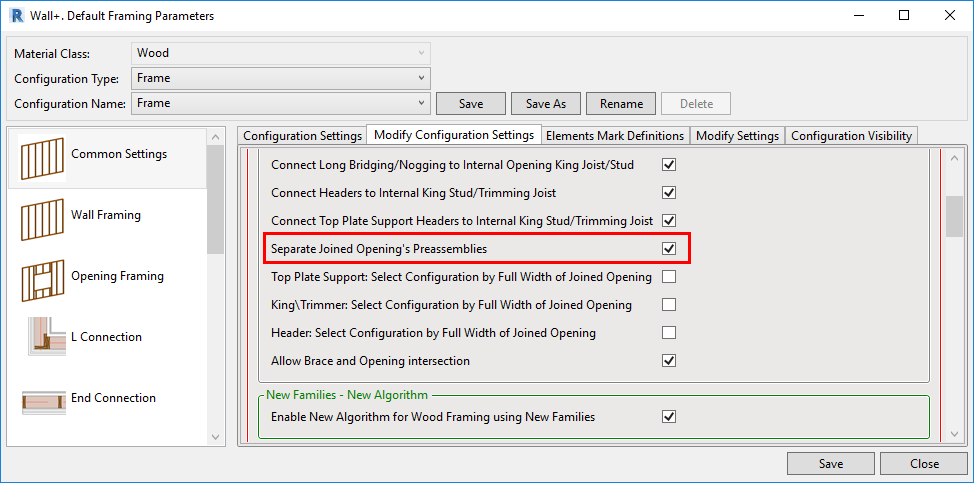
1. Separate Preassemblies for Joined Openings
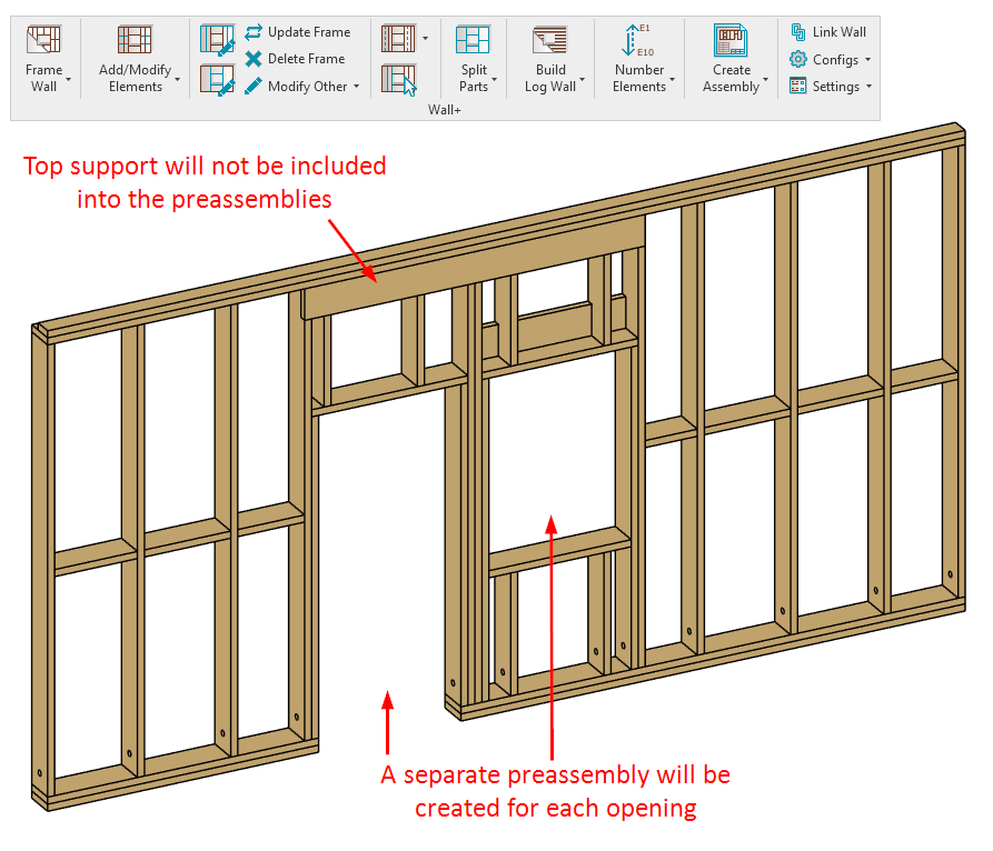
This feature lets you make separate preassemblies for openings that are part of a joined opening — and the preassemblies will exclude other elements (like top plate supports, etc.) that extend across the joined opening. You can find this option to create separate preassemblies for joined openings in the ‘Modify Configuration Settings’ tab of the Default Framing Parameters window:
In this example of a joined opening consisting of a door and a window, we want a separate preassembly for the door and another for the window. Since the top support runs the width of the joined opening, it will not be included in either preassembly.
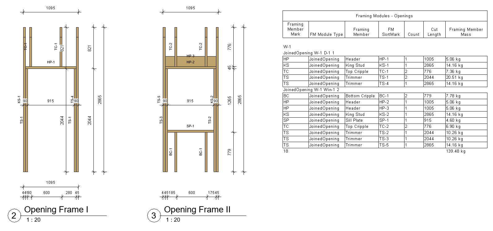
Later on down the road, you can use the Wood/Metal Framing software to create separate shop drawings and schedules automatically, with the help of Revit Filters:
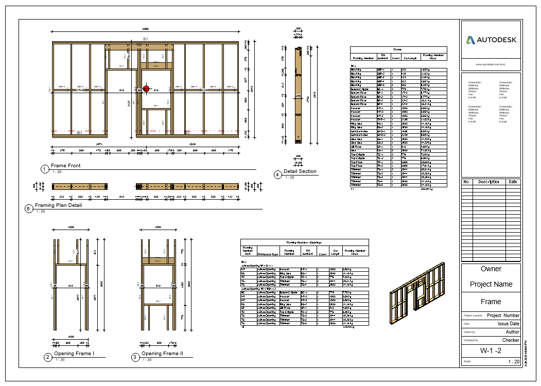
Full Sheet:
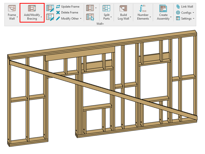
2. Transportation Braces
You can add transportation braces that run across openings. To allow this, just tick “Allow Brace and Opening intersection” in the Framing Configuration:
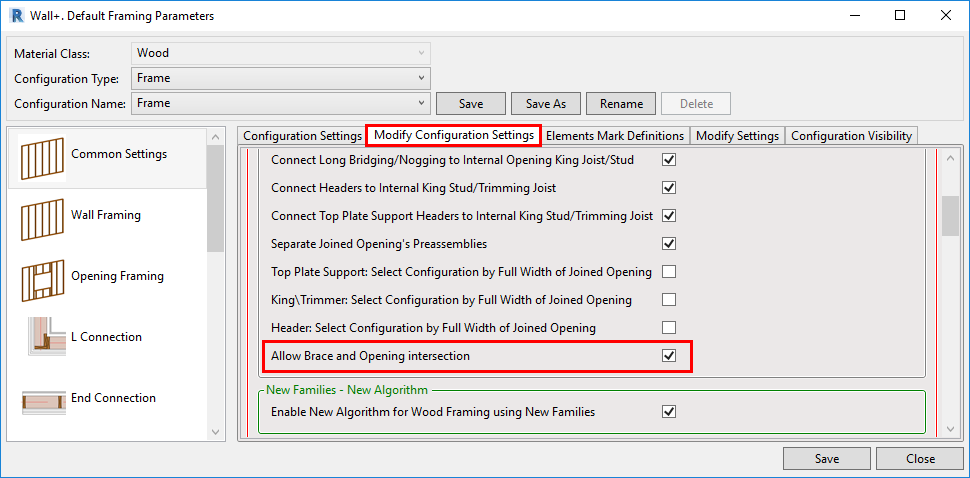
That’ll let you add bracing that runs across the openings:
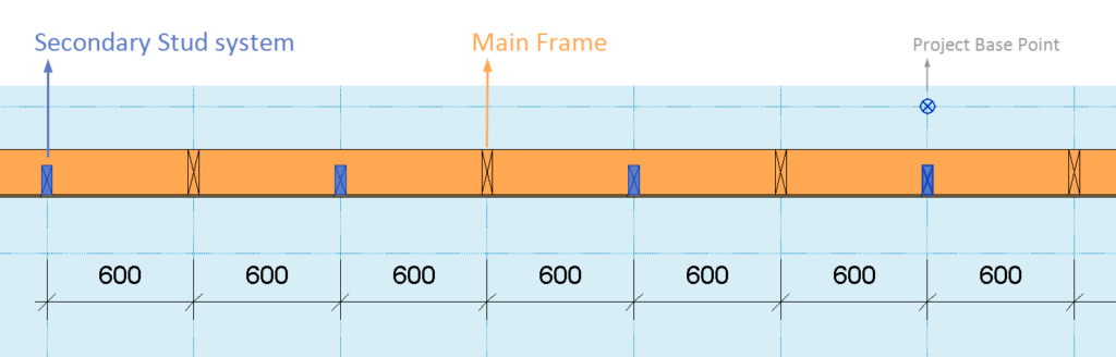
3. Align Secondary Stud System with Project Base Point
You can align a Secondary Stud system with the Project Base Point. In the past, this feature was available only for the Main Frame.
With the ‘Align with Project Base Point’ feature, you can space and align all studs at the same time. Project Base Point now handles positioning in a more robust manner: instead of directly defining the spacing only between the studs, you also define the grid spacing, and the function takes care of the rest. Studs from the Main Frame and Secondary Stud system are positioned on the gridlines, so that they always match throughout the whole project.
Notice how the studs of both the Main Frame and the Secondary Stud system are spaced according to the grid:
How do you use this new feature?
The first step is to unclip the state of the Revit Project Base Point and move it to the needed position:
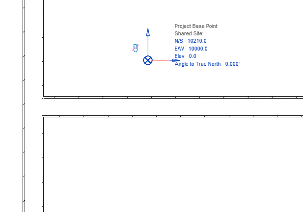
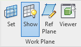
For more convenience, turn Revit Work Plane’s visibility ON and move it to the Project Base Point.
It will help you determine whether studs or joists have been created in the right position. Finally, turn ON ‘Align with Project Base Point’ in the Framing Configuration dialog:

And frame!
4. Additional control over Brace Groups
More features have been added to Brace Groups, allowing you greater control over complex combinations.
5. Partial Brace Groups
A feature called Partial Brace Group lets you create what we call a partial brace group. To use this feature, you need to select four elements as bounds for the group: so two studs and two horizontal elements. That way the Brace Group will be created only between those four elements (not the whole height between studs).
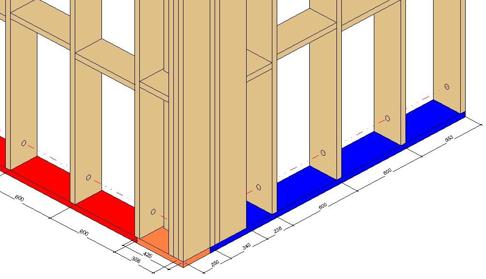
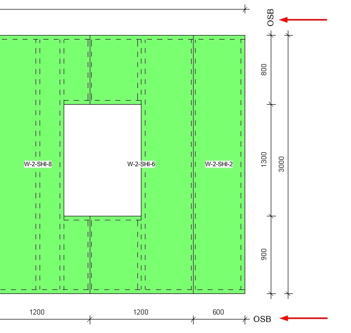
6. Special Layouts for Paneling, additional Splitting Options
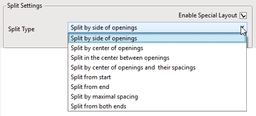
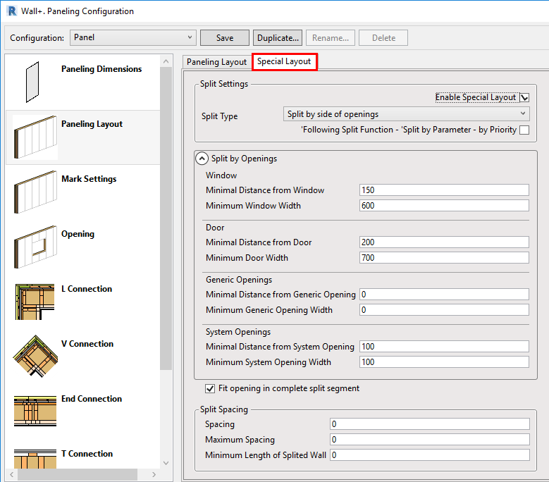
You can ‘Enable Special Layout’ and choose between available Split Types:
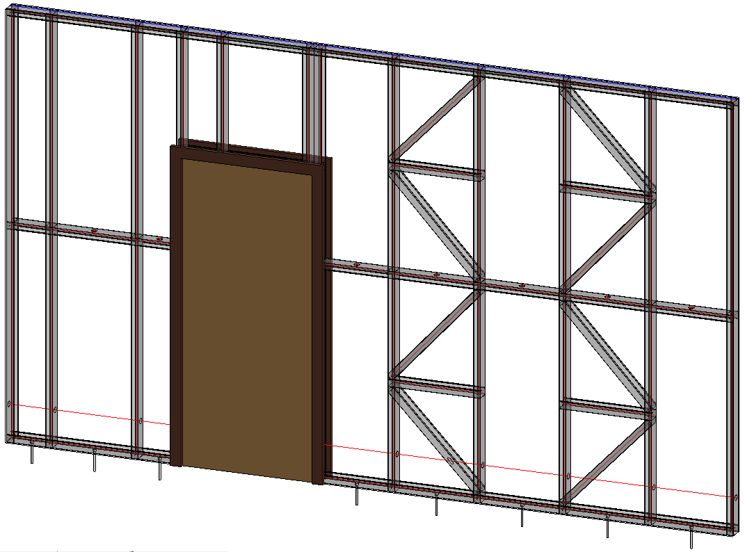
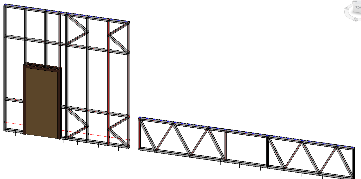
For example, if we select ‘Split by side of openings’ and enter ‘Minimal Distance’ and ‘Minimum Width’ values for windows, doors, generic openings, and system openings as shown in the Special Layout tab below…
…we can get a result like this:
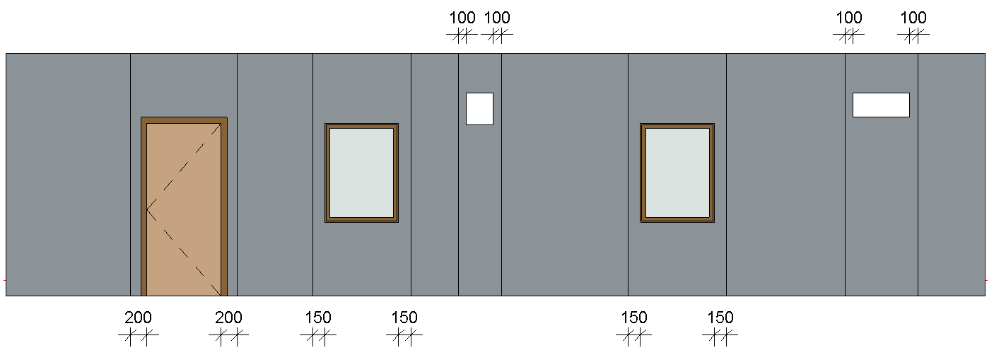
7. Minimum dimensions for framing openings
You can enter minimum dimensions to indicate which openings should be framed:

If an opening’s width or height does not meet the threshold, then that opening will be ignored in the framing process:

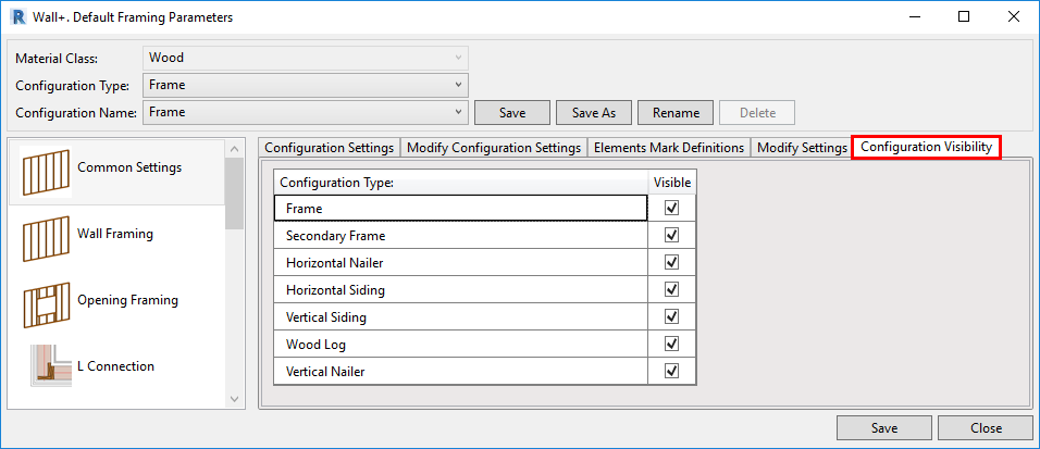
8. Toggle visibility of configuration types
There’s an option that lets you control whether and which Configuration Types are visible. Visibility was added to Wood Framing Wall+, Floor+ and Roof+. That means you can turn off the visibility of unneeded configuration types (Secondary Frame, Nailers, Sidings, etc.), and they won’t appear in the ‘Framing Configuration’ and ‘Link Wall’ windows.
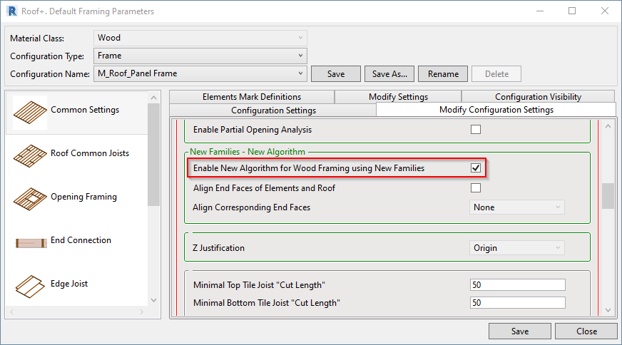
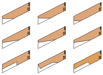
9. Reduced number of Roof+ families but more flexible and intelligent
The new families are easier to use than the old ones that they have replaced, and you’ll find that they greatly expand your framing possibilities.
Example: All these different blockings and headers were created using just one family:

To work with the new families, go to Framing Configuration → Common Settings → Modify Configuration Settings and tick ON the Enable New Algorithm for Wood Framing using New Families.
Advantages of the new families:
- The new families are simple and speed up roof framing by a factor of 2.
- The new families replace and expand the possibilities of the old families.
- The new framing technology is more flexible, making it possible to get good results in all situations faster than using the old families.
Read more about the new and improved Roof+ families here or watch our webinar about them.
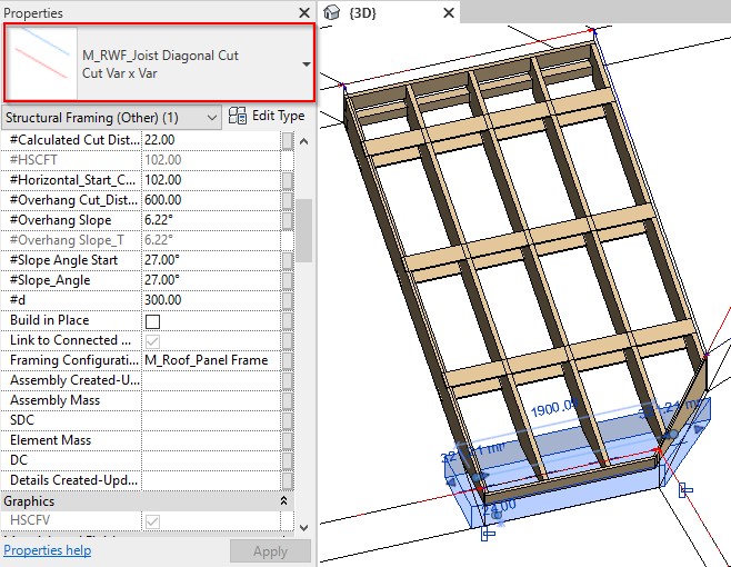
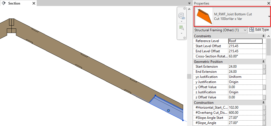
10. New cutting technology for Roof+
This update allows you greater control over joist ends, enabling lots of possibilities. It gives you speed and flexibility when working with ends of elements.
There are 2 new intelligent families used for cutting.
| If the units of your Revit project are… | …then the names of the 2 families are: |
| Imperial | I_RWF_Joist Diagonal Cut.rfa and I_RWF_Joist Bottom Cut.rfa |
| Metric | M_RWF_Joist Diagonal Cut.rfa and M_RWF_Joist Bottom Cut.rfa |
Here are some examples:
Diagonally cut family
Bottom cut family
Watch our webinar about framing timber roofs with rafters and prefab panels in Revit.
11. New framing direction option for Roof+
We’ve added the possibility of aligning the whole framing direction with the roof slope arrow. It allows you to work with different roof shapes and forms.
Watch our webinar about framing timber roofs with rafters and prefab panels in Revit.
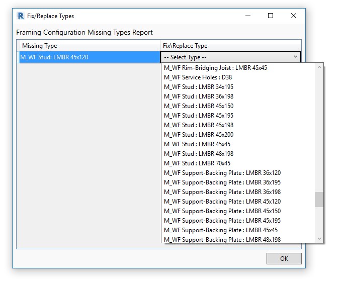
12. Efficiently fixing or replacing Types in Configurations
At the bottom of the Missing Types Report window, there is now a button named ‘Fix/Replace Types in Current Configuration’.
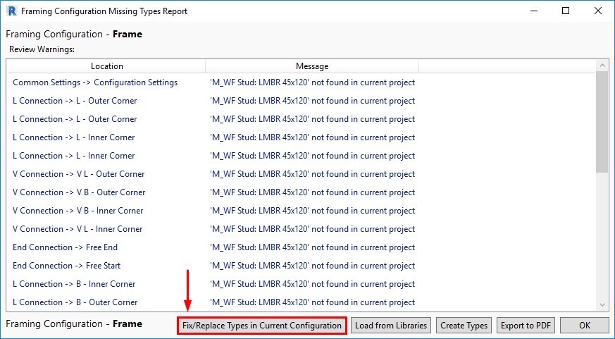
This new option lets you quickly place missing families or types in the project, making the Missing Types Report much more useful because you can efficiently resolve the issues that it finds.
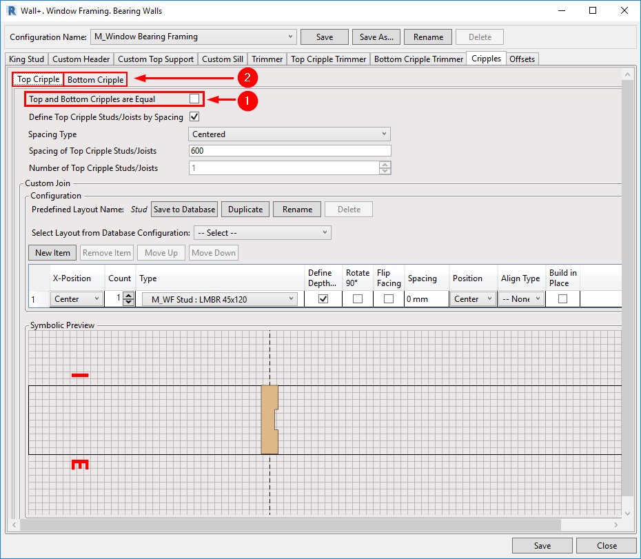
13. Better control of Top and Bottom Cripples
This new option lets you quickly place missing families or types in the project, making the Missing Types Report much more useful because you can efficiently resolve the issues that it finds.
Window, Door, and Opening Cripples have been separated into Top Cripples and Bottom Cripples. After you untick ‘Top and Bottom Cripples are Equal’, two tabs will appear for creating Top and Bottom Cripple layouts. And you have additional flexibility in creating Custom Joins with the help of the symbolic preview window:
14. Link Database configurations together
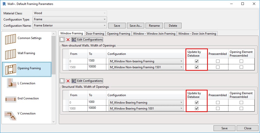
Working with Database Configurations is way more efficient because you can link configurations together throughout all parts of your framing configurations to reflect changes made to any one database configuration. You can find this setting in the Modify Settings tab. Tick ‘Enable “Update by Database” in Custom Joins’.

Then, a new column – Update by Database – will appear in all Custom Joins. Below, for example, you can see the new column in the Window Framing tab:
15. Flexible management of Plates in connections
The efficiency of controlling top and bottom plates in L, End, V, and T wall connection types has been increased. This new feature allows you to fully control both top and bottom plates in wall-to-wall connections and brings more independence to each plate behavior within the wall frame. Wall plate assemblies consisting of single or multiple plates can be cut short, extended, or split up to a selected wall stud. Alternatively, you can input values and lengthen or shorten plates to a specific dimension. It delivers more control and versatility to complex wall-to-wall connection types and adds another layer of control to the already extensive set of L, End, V, and T configuration parameters.
In this example, you can see the setting used an L Connection:
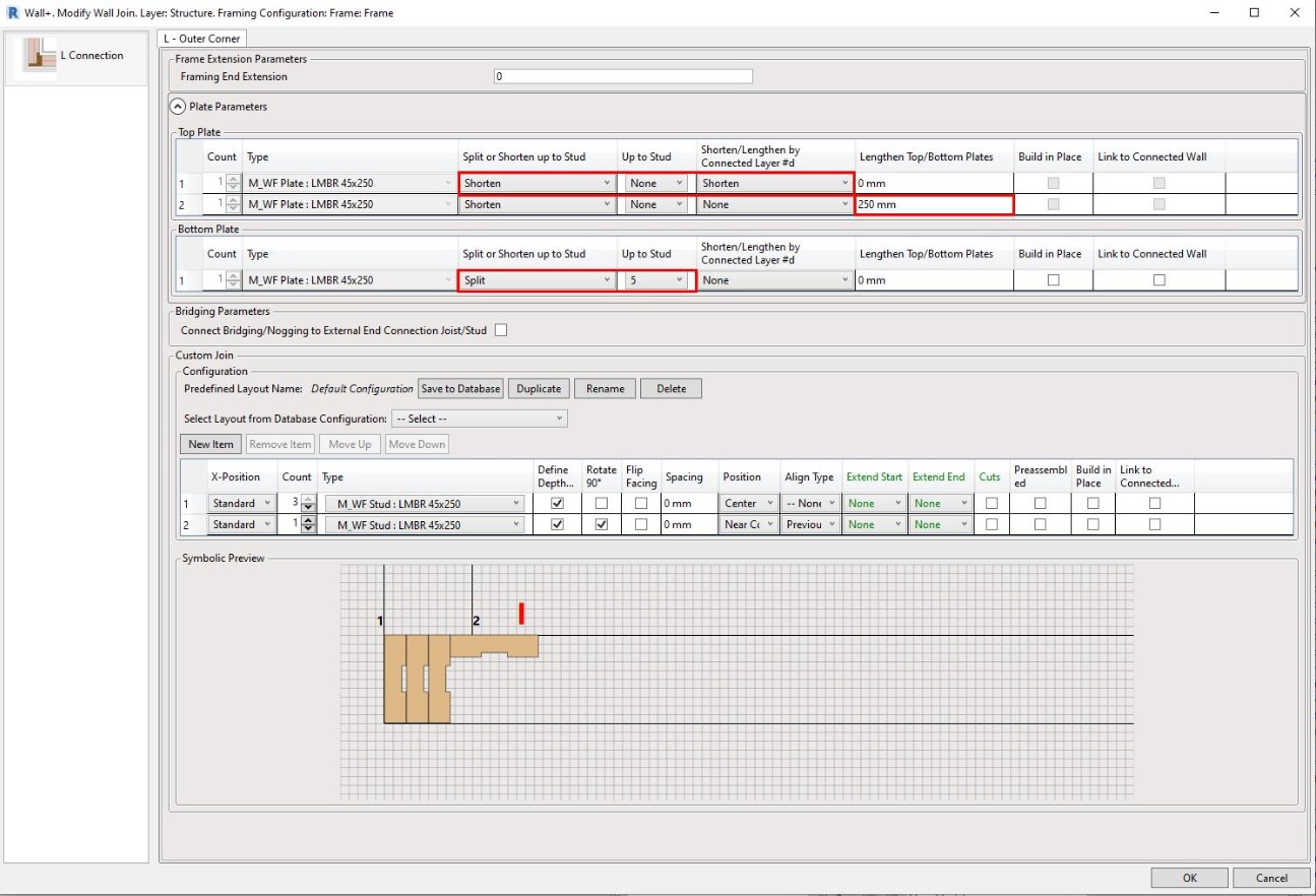
Result – Top Plate:

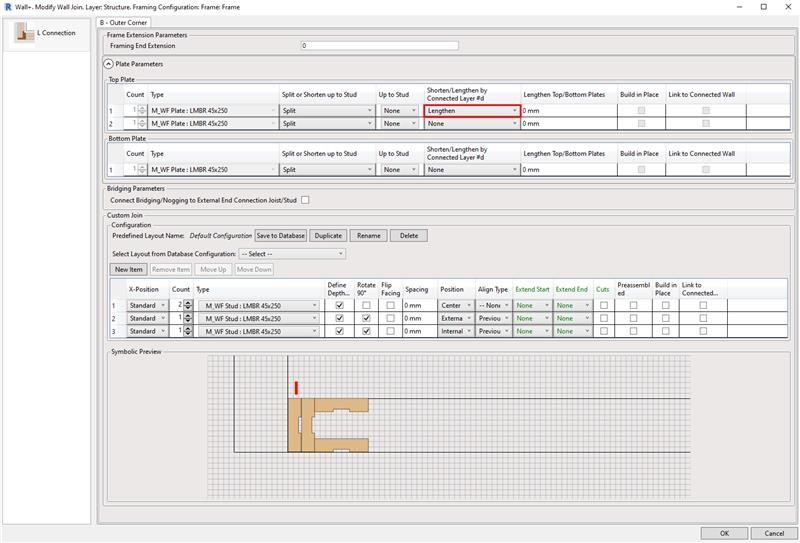
Result – Bottom Plate:
16. Increased Split Elements functionality
Acting on customer requests to expand the Split Elements toolset so that elements that have already been split may be deleted, we have added a new command that allows you to delete splits and delete bridging/nogging elements that have been split. When dealing with bridging/nogging elements, like horizontal siding, you can now delete unwanted siding board cut offs using the ‘Delete Plate or Bridging/Nogging’ command from the Cut/Delete/Move/Rotate Elements menu.

Result:
17. Opening Configuration by Family Type
A possibility to control the Opening Configuration by the family ‘Framing Configuration’ text parameter has been added our framing software. After entering an Opening Configuration name in the Type Parameters, the opening will be framed based on the rules of that configuration, instead of the one that is mapped in the Wall Link:
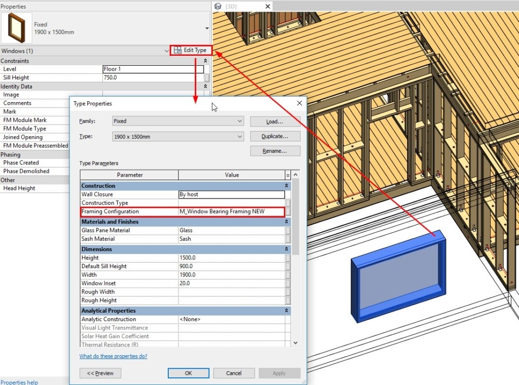
That way, you can frame openings based on their Family Type, and not just their width, as was previously the case.
18. Reconfigure sheathing and paneling
Another great update is the ability to modify sheathing and paneling by choosing a different configuration:
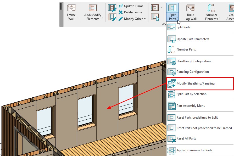
Before the update, you could only modify the configuration that was used to split parts, but now you can select a different configuration for Sheathing/Paneling:

19. Create or exclude parts with Frame Wall
Controls have been added so that you can create or exclude parts with the ‘Frame Wall’ command:
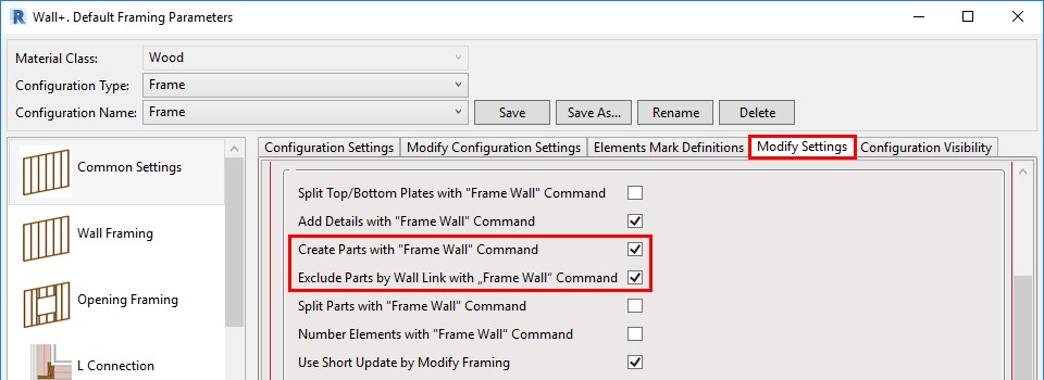
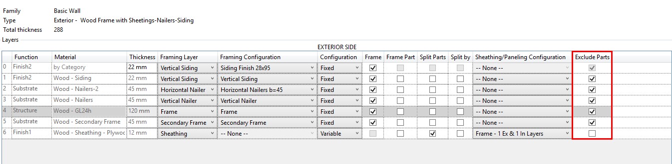
If ticked ON, then the parts will be created or excluded with the ‘Frame Wall’ command, based on the settings in the Wall Link:
20. Cut Plates and Siding with Additional Opening Voids
An option for cutting Bottom Plates with a void in an Opening family has been added in the ‘Modify Settings’ tab:

If ticked ON, then Bottom Plates will be cut by intersecting Opening families that have a void in them.
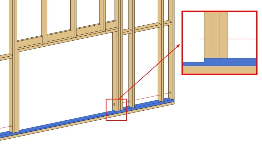
Siding Boards can also be cut by a void:

Bottom Plate cut by an additional void:
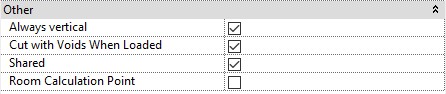
Note that ‘Cut with Voids When Loaded’ must be ticked ON in the Opening family:
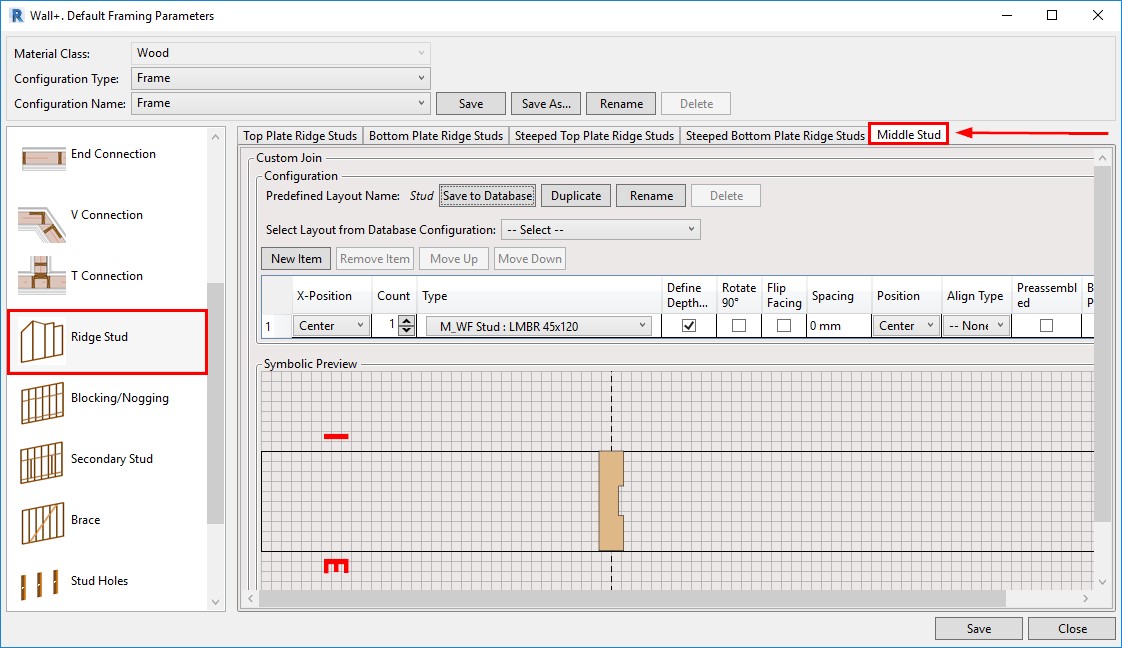
21. Add a Mid-ridge stud
Another client request came true with this enhancement. A new option in the Ridge Stud tab has been added to the framing tools: ‘Middle Stud’ – it’s for adding Studs in the center of the Wall automatically:
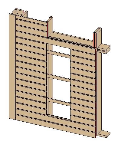
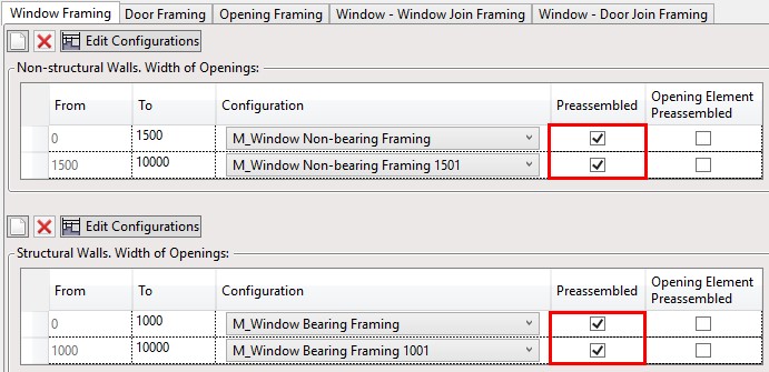
22. More options for preassembled openings
This improvement will be useful for those who work with preassembled openings. Elements that you add through the ‘Blocking/Nogging’ tab and that have Placement limits set to Openings (Windows, Doors, etc.)…
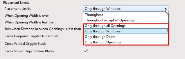
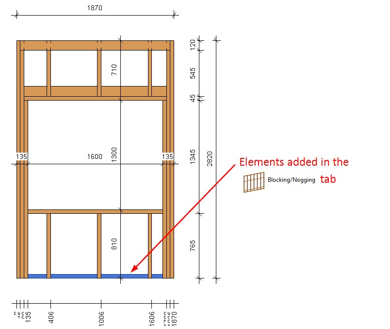
…will be added to the Openings Preassembly automatically if the Opening is marked as preassembled:
Result:
23. Add more tabs for dimensioning rules
From now on, you can create dimensioning configurations in multiple dimensioning rule tabs for same-category elements:
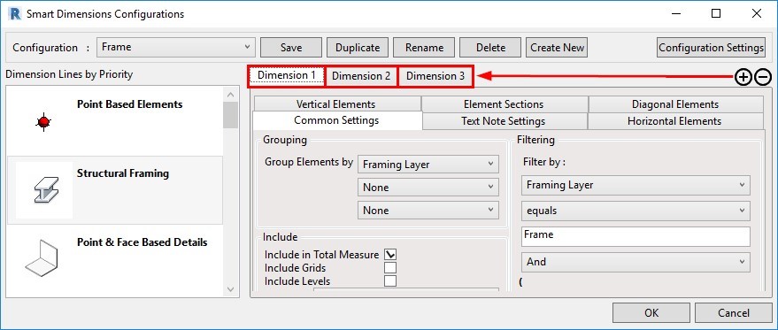
That will lead to more options and flexibility using filters and other settings.
24. Auto-dimension part openings
You have the option to dimension part openings automatically using Smart Dimensions. A new tab named ‘Part Openings’ will appear after creating a new dimensioning configuration:
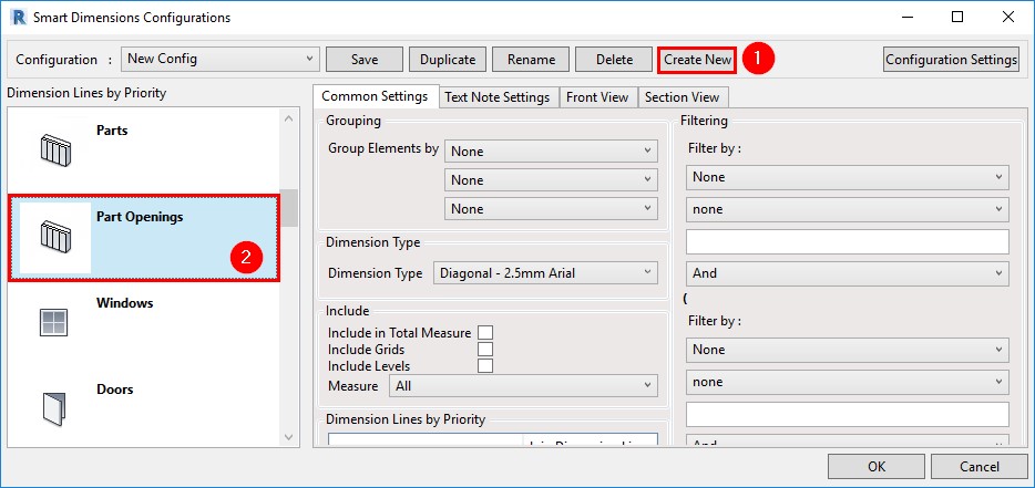
As a result, part openings will have their individual dimensions that are not tied to Structural Framing elements:
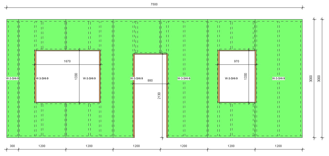
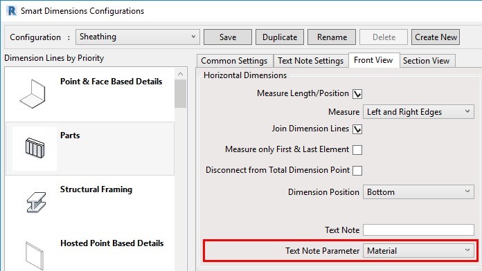
25. Use material as a text note parameter
The option to use ‘Material’ as a Text Note Parameter in Smart Dimensions was added:
In this example, you can see that the sheathing layer material Name was added to vertical and horizontal dimensions:
26. Placement of assembly views
We have made improvements on where assembly views are placed. Now, view positions are aligned by views placed in the Sheet Template. After creating an assembly for which sheets are going to be used as Sheet Templates, you can modify the positions for, let’s say, Plan and Section views:
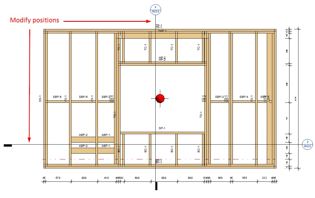
After sheets for this panel have been created and set as templates, all future assembly views will be created based on these modified view positions.
27. Disable analytical lines
A Type parameter was added that lets you disable analytical lines for specific elements, like service holes and invisible elements:

If ‘Disable Analytical Model’ is ticked ON, then the ‘Enable Analytical Model’ instance parameter is automatically turned OFF once the elements are distributed:
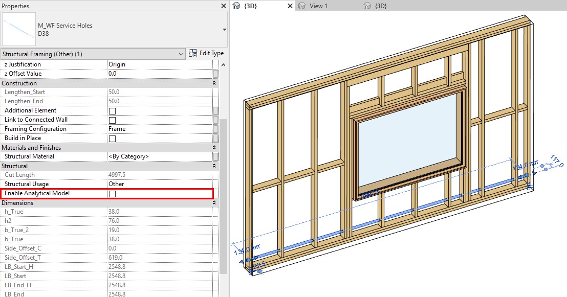
This means that those specific elements will not be exported to, for example, Autodesk® Robot® for structural load analysis.
28. Framing in Groups

The Framing in Groups functionality allows you to frame walls in groups. Use this valuable feature to repeat and mirror framings many times throughout a project. Incorporating this into the framing workflow has the potential to save architects and designers a lot of time.
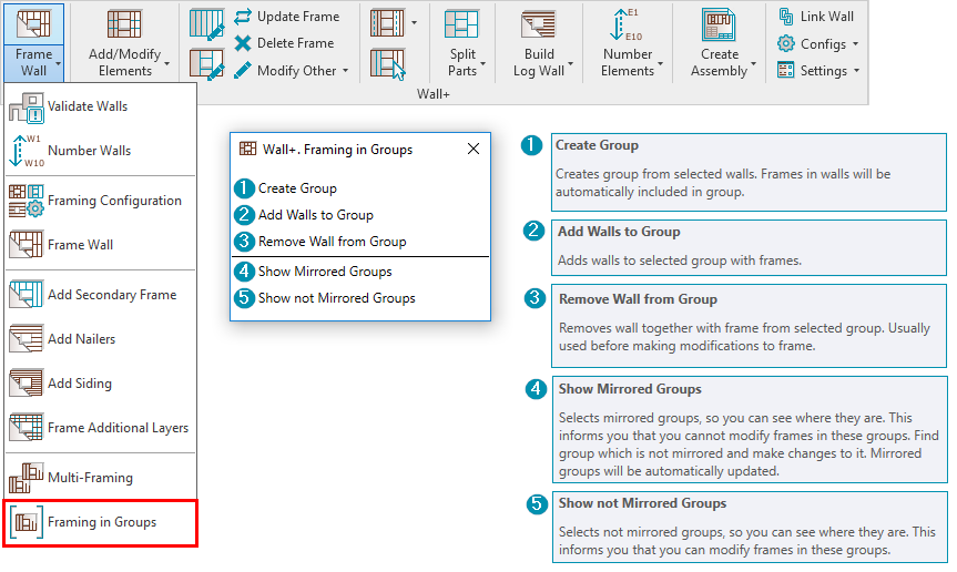
There are five new functions that fall under the Framing in Groups feature, as seen above. Read more about each one in this blog post.
You can also see the features in action in our webinar Multi-Framing with Model Groups in Revit.
29. Transfer Host Mark Value into Parts When Number Parts is Used
The Host Mark parameter value will be transferred to Parts – Sheathing/Paneling, after using the ‘Number Parts’ command:
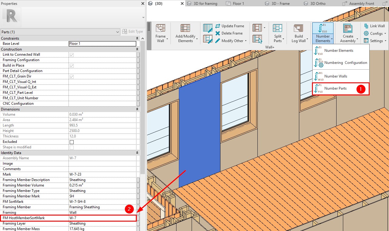
You can take advantage of this enhancement if the Host Mark parameter value will be changed after the Parts have been split because you won’t have to Split the Parts again.
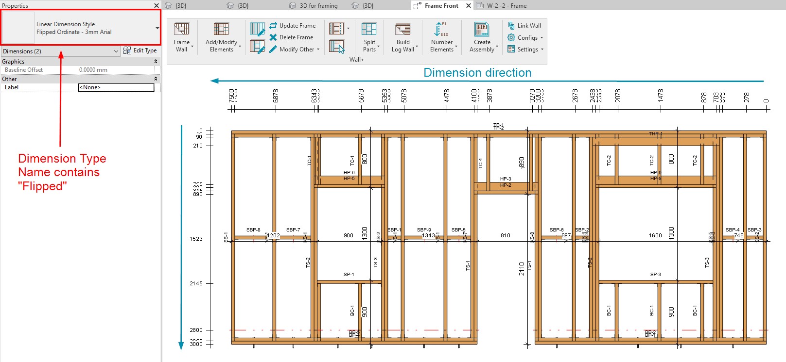
30. Flip Ordinate dimensions
If the Ordinate Dimension Name contains “Flipped”, then the elements will be numbered in the opposite direction.
For example, these are the results of a view with an Ordinate Dimension whose Type Name…
…does NOT contain “Flipped”

…DOES contain “Flipped”
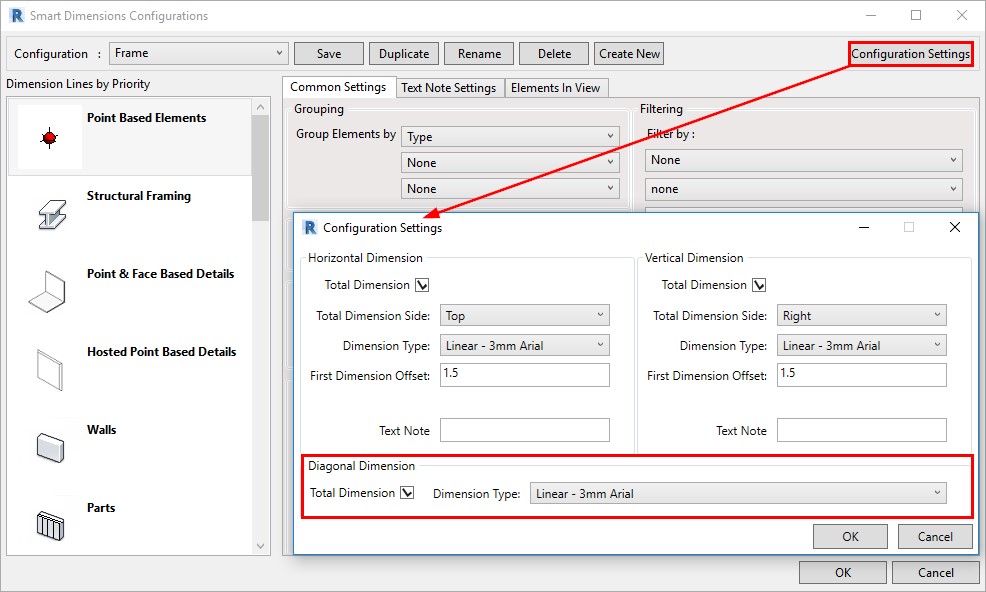
31. Total Diagonal Dimensions
You can add a diagonal Total Dimension with the help of Smart Dimensions:
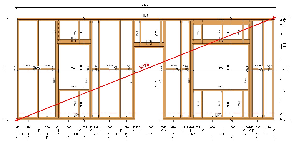
Result:
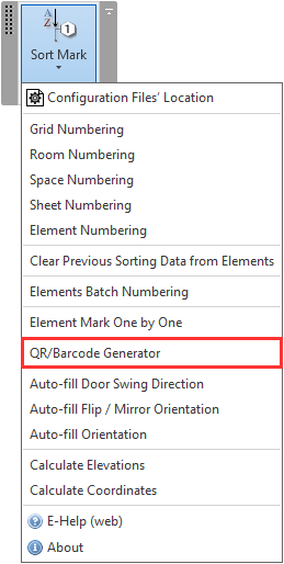
32. QR/Barcode Generator added to Sort Mark Revit Tool
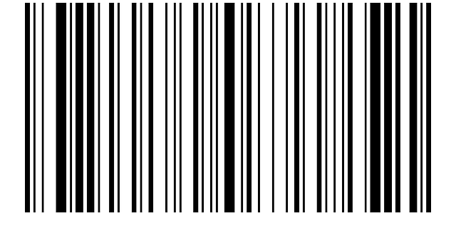

We added a new feature to our Sort Mark tool for Revit that allows you to generate QR codes or barcodes that can be placed on your shop drawings in Autodesk Revit.

One of our T4R Add-ons, Sort Mark, is a powerful plug-in that automates sorting and numbering in Revit. In addition to renumbering elements the way you want, it can also detect and renumber grids, determine swing direction and orientation of doors, recalculate shared coordinates, and more.
Since you can place any information you want into that QR/barcode, the possibilities are vast, as it can ensure better quality control, enhance collaboration between teams, or speed up the manufacturing process.
The idea behind this new feature is to generate a code as an image based on your selected parameters (you can also crop the values of those parameters, add suffixes, prefixes, etc.).
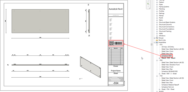
The newly generated image is placed by default in the Image type parameter, but you can create any parameter in which the image should be placed.
To see that QR or barcode, you need to make a Schedule with that Image parameter selected and drop that schedule in your drawings. You can do that manually or automate it by using AGACAD’s shop drawings BIM tool.
In the example below, you can see QR codes and barcodes generated for assemblies:
In this blog post and video, we explain and show how to generate QR and barcodes using Sort Mark.
Want to find out how our framing solutions can streamline your Revit workflow?
Our professionals are here to help.

Contact us for a free, live demonstration given online by one of our BIM experts. Although you’re more than welcome to download a free trial, we encourage you to have a free demo first. That way you’ll be in a better position to evaluate the software during your free 14-day trial period since you’ll already have answers to your preliminary questions and feel more comfortable with the basic workflow.
Want to know more about our software for framing timber and steel walls, floors, trusses, rafters, and prefabricated roof panels in Revit? Click one of the banners below to read more about it!