
By Povilas Sindriūnas, AGACAD Architectural Engineer & BIM Application Engineer

Working with volumetric massing in the early phases of a new project benefits all parties involved, like designers, developers, planners. It helps convey the key ideas behind the design intent and better understand the relationships between the new building, the site, and immediate built environment. Wouldn’t it be handy to be able to build your project on the finalized and agreed upon volumes of the future building? In the third part of this Revit Massing series, we’re going to discuss how you can continue modeling from the conceptual massing stage right through to detailed design and also be able to coordinate it with other consultants involved in the project.
In the previous articles, we talked about the difference between an in-place mass and a mass family and how to create a conceptual mass family in Revit. Part III here will focus on how to generate Revit elements based on an existing in-place mass family. Before we proceed, let’s recap the main difference between two mass types in Revit.
In-Place Massing (in project) Massing & Site > In-Place Mass | Conceptual Massing Environment (outside project) Revit > File > New > Conceptual Mass |
In-Place Mass Family
In-place massing is carried out directly inside the project environment.
- This allows you to see the rest of the project context very useful in the early design stages.
- It’s the most straightforward approach and works well when the building volumes are not too complex.
- Good for preliminary sketching of forms and is the recommended approach for early stage design and for conceptual building studies.
Conceptual Mass Family
The family is built in the ‘conceptual massing environment’, outside the project environment.
- Iterations of the family can be placed as needed around the site.
- The family can be loaded into multiple Revit models.
- Different team members can work on different versions of the family.
- Better for developing and refining a building mass. The separate environment has additional visibility of 3D levels and reference planes, which makes more complex parametric modeling easier.
Applying Geometry to Revit Masses
Revit geometry (i.e. walls, floors, roofs) can be added to the face of any mass object. In this example, we are going to use an In-place mass family that we produced back in Part II. To model elements by 3D face of an existing mass, follow the sequence below.
- Go to the ‘Massing & Site’ tab.
- Select ‘Floor’ category from ‘Model by Face’ menu.
- Choose desired floor type and offset from level.
- Select one or multiple Mass Floors.
- Select ‘Create Floor’.
Note: Mass floors were placed at each level or at selected levels. Revit floors will be generated in those exact locations.


1. Select a single or multiple mass floors within the mass family.

2. By selecting ‘Create Floors’, new floors will be generated in place of mass floors.
The great thing about applying geometry to masses is that you can choose the types of elements you want to use according to its composition and identity parameters. It’s important that you create floor types according to the structural characteristics and overall composition required by the project. Floors can later be modified or changed to different types.


 1. Choose floor type and select mass floor. |  2. Select ‘Create Floor’. |  3. Floors generated in place of mass floors. |
Note: As with a typical floor, edge profiles can be edited. You can further place shafts and floor openings.
Once the floors have been created, you can hide or delete mass floors if no longer needed. Filter out all mass floors and hit delete.


Note: Floors can be isolated and edited.
The next step is to apply remaining elements, like roofs, walls, and curtain wall panels. To do that follow these steps.
- Go to the ‘Massing & Site’ tab.
- Select ‘Curtain System’, ‘Roof’ or ‘Wall’ respectively from ‘Model by Face’ menu.
- Choose the desired element type according to its build-up and composition.
- Define wall insert parameters like location line and join status.
- Select 3D face(s) of a mass using ‘Pick Faces’ tool.
- Click ‘Create System’ or ‘Create Roof’ button. Elements will be generated in place of the 3D face.
Note: Newly created elements are going to reflect the geometry of the 3D face. Massing faces are not deleted and remain for future use.

 1. Choose a 3D face by ‘tabbing’ for the right one. |  2. Choose 3D face for the roof or curtain system. |  3. Curtain systems & walls can be customized. |
Applying Curtain Systems to Masses
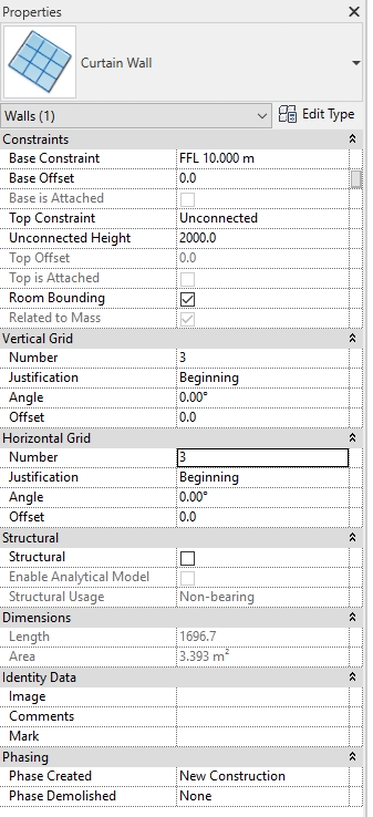
A curtain wall system can be applied to mass faces and will work with more complex geometry such as curved faces. Both system panels and curtain panels can be specified in the curtain system. When dealing with curtain walls and curtain systems, you can customize an entire wall or system by going to family type parameters and defining horizontal and vertical grid placement, mullion types, etc.

Note: The profile of newly created curtain wall can be edited to create more unusual panel shapes.
If the mass is updated or modified (e.g. its profile is altered), then the Revit geometry will need to be updated to suit the changes. This is a simple process.
Steps:
- Select the wall(s) – right click ‘Select all instances’ if you want to update several in one go.
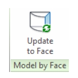
- Click on the ‘Update to Face’ tool.
Note: There are limitations with this tool. It is often quicker to select the walls/curtain walls and delete and reapply to the altered mass.


The ‘Show Mass’ button turns the visibility of all mass elements ON/OFF. ‘Show Mass by View Settings’ displays the mass as per the setting in the Visibility Graphics (VG) dialog.
 1. Select 3D face of a mass to generate a curtain wall system. |  2. Curtain wall system is placed according to existing shape and geometry of 3D face. |
Applying geometry to masses in Revit is a great way to quickly build models and address key conceptual issues. Once volumes are generated and resolved to a desired level, they can be shared among colleagues and consultants. At this point, the entire model can be made collaborative by creating Revit worksets and a central file. Models can also be split to reduce file size or to break down the building into sections for a larger project. It can also be split to serve each discipline, e.g. MEP, facades, architectural, landscape, structural, etc. Another way would be to use central model as a container file and link all other models into it.

1. Typical architectural views can be created (levels can be added or removed ).

2. Grids can be placed at structurally significant junctions and further manipulated.
Building Revit elements upon existing massing allows you to further progress the design to the next phase. By now you can generate views and produce drawings as in a typical Revit project workflow. Drawing packages can be exported and shared for coordination purposes. Models can also be exported to various formats including IFC and be shared and essentially become BIM enabled projects. At this stage of design, you can go into more detail and work on structural aspects of the building as well as façade design using Revit curtain walls and systems parameters.


 1. In-Place Mass family |  2. Geometry applied to mass using ‘Model by Face’ functionality |
Subscribe to our BLOG newsletter and stay updated on upcoming free webinars, Revit tips & tricks, and the latest news on AGACAD TOOLS4BIM development and applications!
Related blog posts:
- Revit Massing (Pt. I): In-Place Mass vs Mass Family
- Revit Massing (Pt. II): Creating a Conceptual Mass Family
- Common Types of Roofs & How to Model Them in Autodesk Revit
- From Conceptual Mass to Shop Drawings in under 30 minutes [VIDEO added]
- From Conceptual Mass to Structural Framing with Wood/Metal Framing Floor
- Designing Precast Concrete Parking Garages in Revit [WORKFLOW+VIDEO]
- How can roof design and manufacturing processes be improved by automation? [VIDEO added]
- Maintaining a healthy Revit model (Part I): Revit’s inbuilt warning system and audit tool
- Maintaining a healthy Revit model (Part II): keeping Revit warnings to a minimum
- Maintaining a healthy Revit model (Part III): factors that make models fail PLUS how to up your Revit game!
- BIM Content Management & Classification: the case for classifying BIM data


