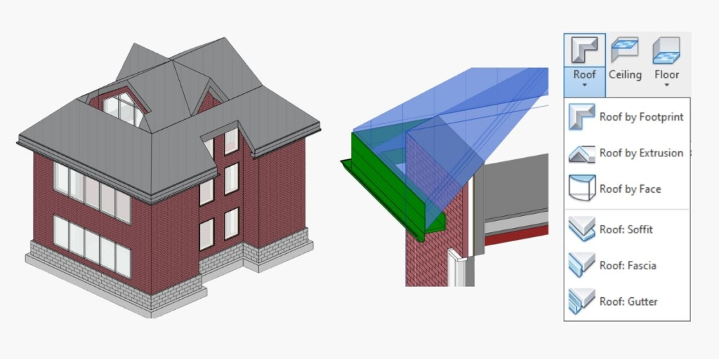
Designing roofs in Revit can pose certain difficulties particularly for users less familiar with roof modeling tools. Creating exact roof geometry and size for a new build or modeling an existing roof to given dimensions is not always straightforward. Some key principles, however, can help model quite a few roofs simply by using Revit’s ‘Roof by Footprint’ tool.
For more complex roof profile shapes, ‘Roof by Extrusion’ is typically used, which we will cover in future articles. Other ways of creating roofs are 3D massing using the ‘Roof by Face’ tool, which allows you to come up with a greater variety of complex roof designs, and In-Place Massing or Mass Families, which allows you to design irregular roofs and tensile roof structures.
For now, we’ll focus on some of the more common roof types used for small-scale residential, commercial, and industrial projects.
Simple hip roof
To create a simple hip roof with the ‘Roof by Footprint’ tool, follow the steps below.
1. Have your perimeter walls and levels ready
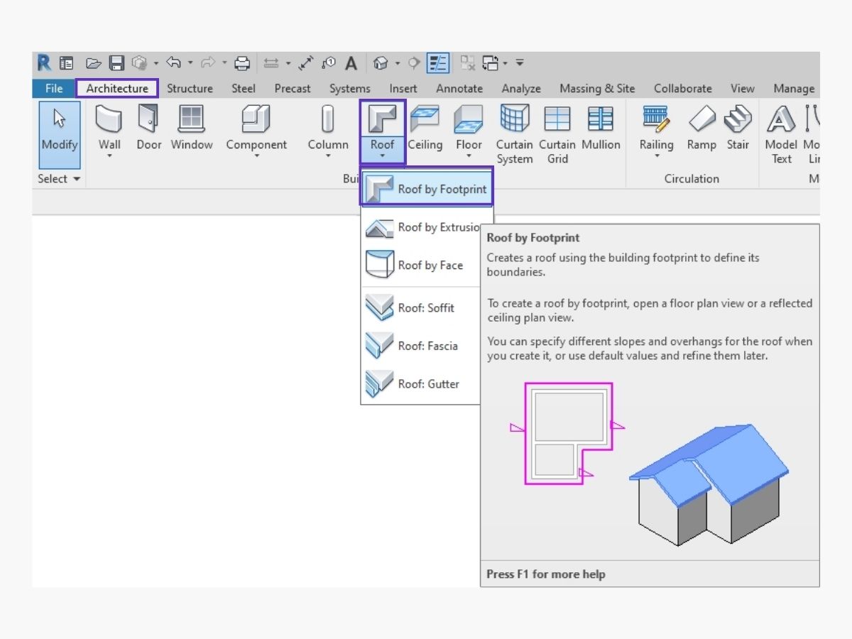
2. In Architecture tab select Roof – Roof by Footprint tool and choose desired roof type
3. Choose a relevant level for a bottom face of the roof

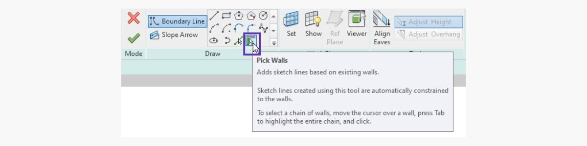
4. Use Pick Walls tools and hover over a wall – press tab to select all joined perimeter walls
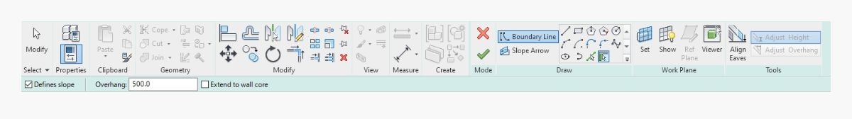
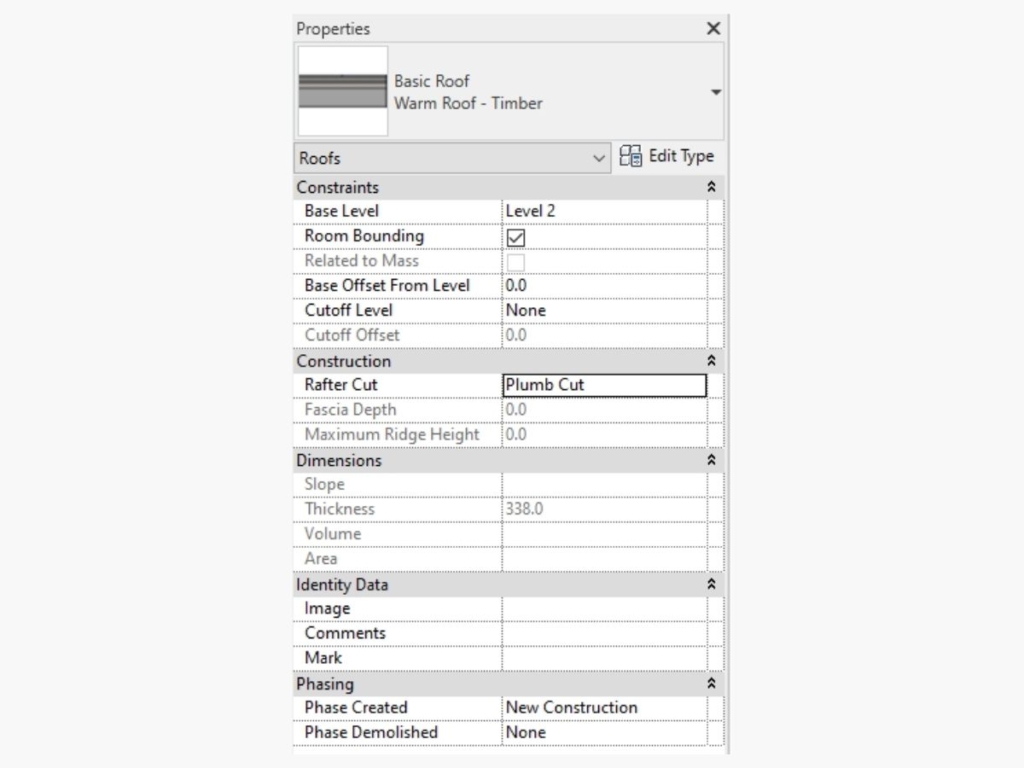
5. Define roof parameters like overhangs, slopes, offset from level, rafter cut
6. Finish the roof by exiting roof editor
- Have your perimeter walls and levels ready
- In Architecture tab select Roof – Roof by Footprint tool and choose desired roof type
- Choose a relevant level for a bottom face of the roof
- Use Pick Walls tools and hover over a wall – press tab to select all joined perimeter walls
- Define roof parameters like overhangs, slopes, offset from level, rafter cut
- Finish the roof by exiting roof editor
 |  |  |
| 1. Use pick walls draw tool. | 2. Each boundary line can be edited individually. | 3. Roof slope is defined in parameters. |
 |  |
| 4. Roof slope may be adjusted using grab handles. | 5. Additional features can be added. |
Variation of a hip roof
For a different variation of a hip roof, follow the same steps given above and adjust a few parameters as shown below.
 |  |
| 1. Roof shape may be further manipulated. | 2. Define overhangs and switch off slope parameter for gable end roof boundary lines. |
 |  |
| 3. Wall can be attached to follow roof line. | 4. Select multiple walls and use Attach Top/Base function. |
Dormer, mono pitch, double-pitch gables
In the next example we will see how dormers, mono pitches, and double-pitch gable end roof types can be modeled using the ‘Roof by Footprint’ function.
To achieve these more complex shapes, again, follow the steps given in the first example and adjust some settings.
 |  |
| 1. Roof pitches can be manually adjusted using grab handles. | 2. Prepare walls and levels for entire house. |
 |  |
| 3. Add roof by footprint by selecting external walls. | 4. For triangular dormers add one boundary line for each slope of dormer. |
 |  |
| 5. Add slope arrows for each boundary line pointing to each other. | 6. Use Slope Arrow from Draw tools set. |
 |  |
| 7. Remove slopes where gable ends are desired (untick ‘define slopes’). | 8. Rafter Cut type, Slope and Constraint parameters can be changed. |

9. Select walls from lower levels and attach to roof. You can also create walls at the relevant attic level and attach them.
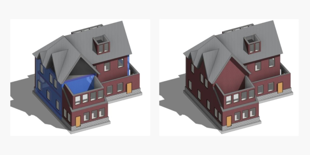
10. To make a double pitch dormer roof, create roof by footprint at corresponding level, untick slope parameter for gable end boundary line, connect corners, draw a new line at the back and switch off slope parameter, and attach gable end wall to roof.
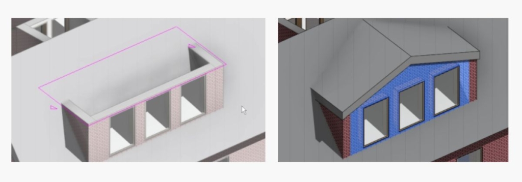
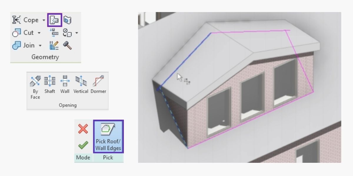
11. Use Join/Unjoin Roof function in Geometry tab and select both main roof and dormer roof – then create a dormer opening for the main roof. Pick roof/wall edges and trim corners of model lines.
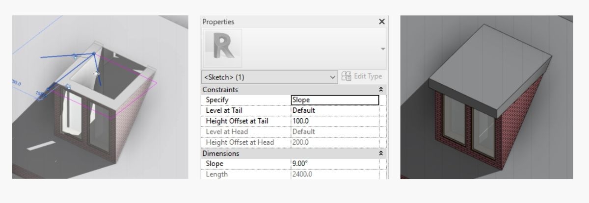
12. For mono pitch dormers repeat the process, but remove slope definition and instead add a slope arrow, which can be further defined in properties.
13. For remaining mono pitches repeat same process, and either use a slope arrow or add a slope to one of the perimeter roof boundary lines. Cut roof openings as in previous example.

14. To create a roof sweep, add roof by footprint and remove slope definition from inner boundary lines. Pitch can be adjusted.

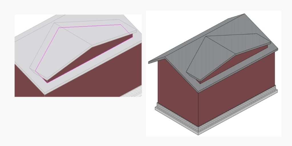
Hip dormer, half hip
To create a hip dormer roof or a half hip roof, create roof by footprint as in previous examples and follow these steps.
 |  |
| 1. Create roof with slope definition for all three external boundary lines. | 2. For a half hip gable end – split entire line into three and remove slope definition for two side boundary lines. |
 |  |
| 3. Define slope for middle boundary line and write in Offset From Roof Base parameter. | 4. The result is half hip roof with dormers. |
Other dormer types
Other types of dormers can be created following the same principles as in previous examples. Use ‘create roof by footprint’ and add additional features as shown below.
1. Pick external walls to create roof – break down boundary lines to define where your dormers will be.
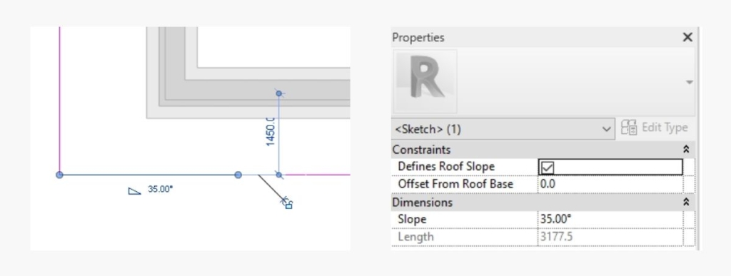
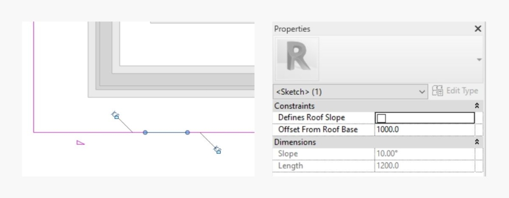
2. Add a 10 degree slope to middle boundary line with boundary lines on each side without slope definition and with slope arrow.
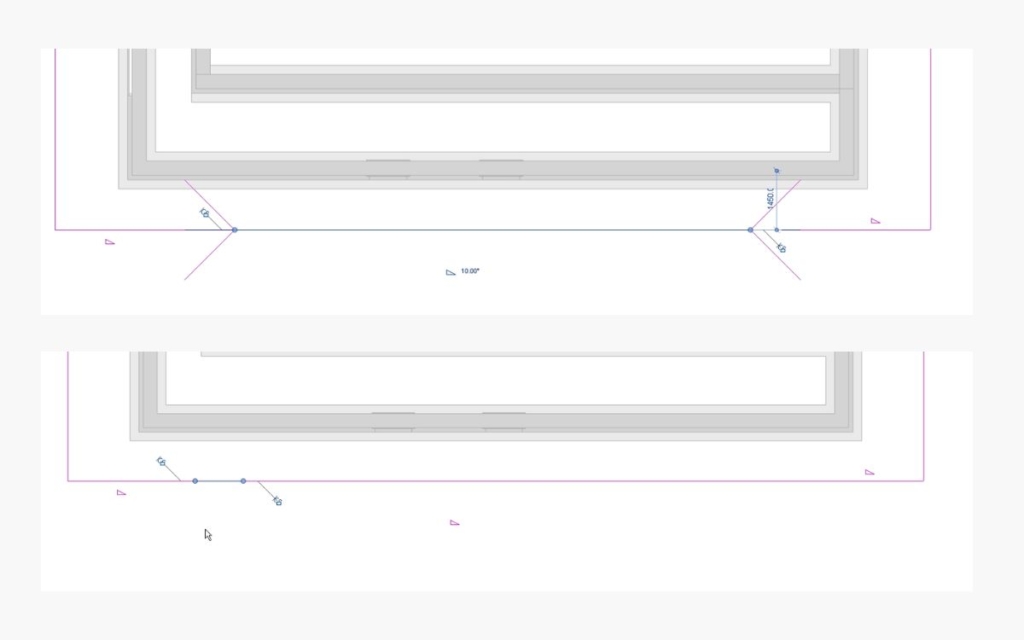
3. Keep a zero offset from roof base for the first and last boundary lines.
4. Gradually increase offset for next two lines going towards the centre – 1000mm offset.
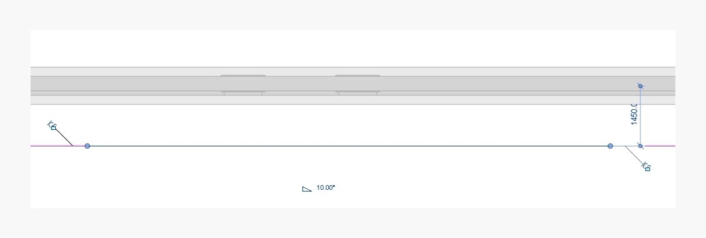
5. Use 1200mm Offset From Roof Base for top of the dormer roof line.
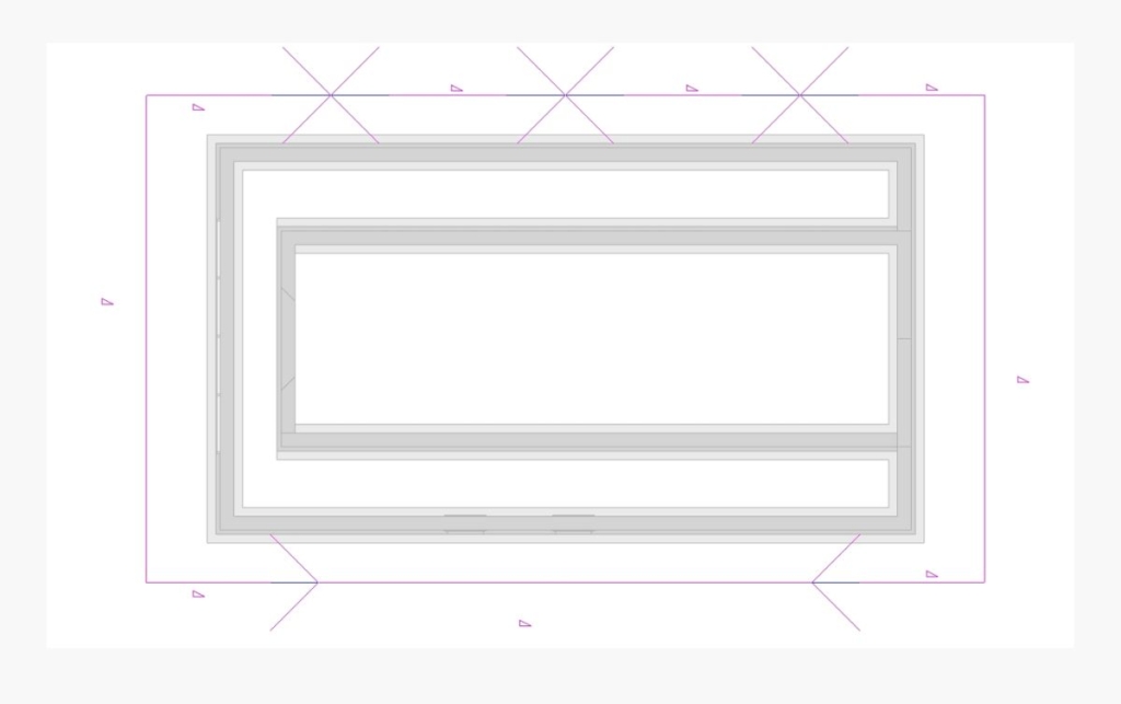
6. Cut dormer opening for the main roof by picking walls within the perimeter.
7. Create roof by footprint for the top piece and attach walls to roof if needed.
8. For inverted roof add negative slope value to side boundary lines.
9. Inverted roofs can be applied to different scenarios and further modified.
Mansard
To model a mansard type of roof, Revit lets you define a cutoff level where roof is cut horizontally and additional roofing can be created from the cutoff level upwards. Let’s look into this more closely using the following example.
 |  |
| 1. Create a new level for roof cutoff. | 2. Draw a roof by footprint and specify cutoff level. |
 |  |
| 3. Specify slopes and overhangs. | 4. Join walls to roof. |
 |  |
| 5. Use rectangle tool to draw new roof by footprint at new pitch angle. | 6. Specify base level at cutoff level. |
 |  
|
| 7. Draw additional double pitch roof at cutoff level. | 8. Cut dormer openings for both roofs. |
 |  |
| 9. Draw walls and attach to both roofs. | 10. Instead of attaching walls to roof alternatively wall profile lines can be edited. |
11. Revit Roof tool set lets you add soffits, fascia, and gutters to an existing roof by picking the roof edge line.
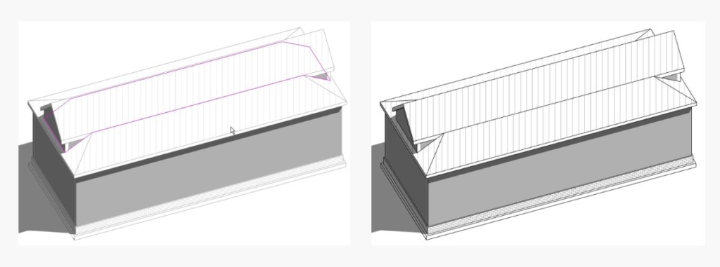
Irregular double pitch
Irregular double pitch roofs are also quite simple to create. Keeping in mind the steps taken in the examples above, draw walls and create roof by footprint at the relevant level.
 | 
|
| 1. Split gable end boundary line in two. | 2. Add slope arrows pointing toward each other |
 |  |
| 3. Define slope arrow parameters. | 4. Prepare dormer walls and draw roof. |
5. Join two roofs and cut dormer opening in the main roof.
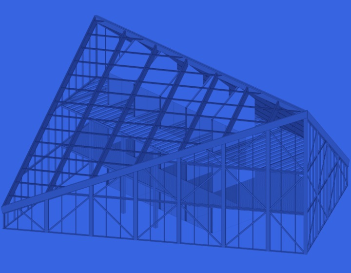
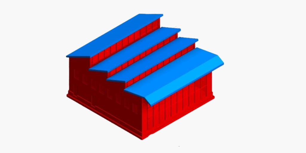
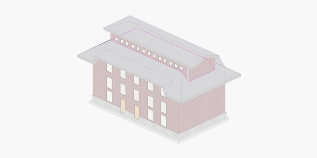
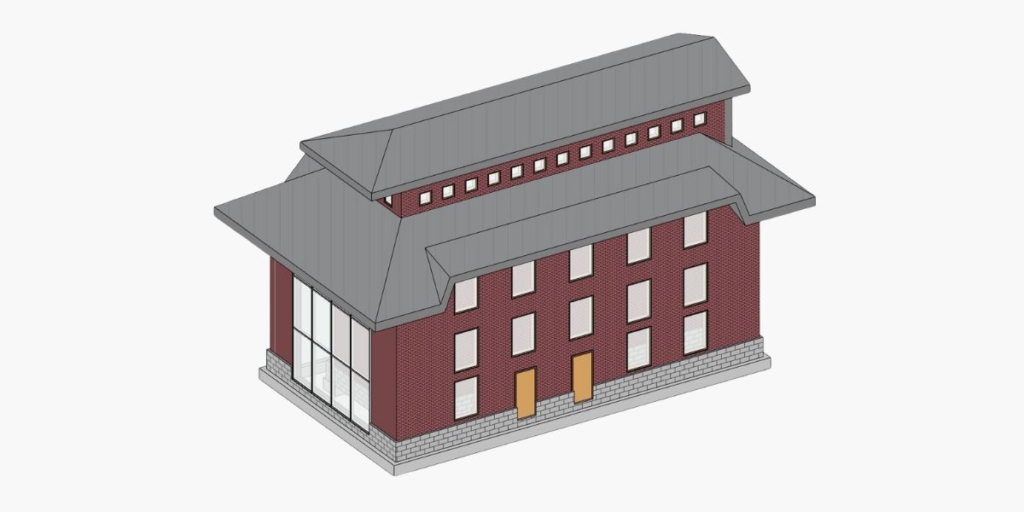
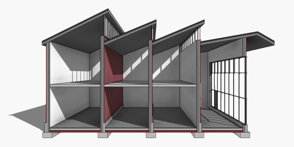
Mono pitch array
Modeling roofs by footprint may also be used for other typologies. An array of mono pitch roofs can be designed so that it allows clerestory windows to be placed at intervals.
 |  |
| 1. Side walls can be adjusted by manipulating profile line to desired roof line. | 2. Draw a roof rectangle and add slope arrow. |
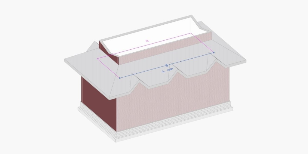
 |  |
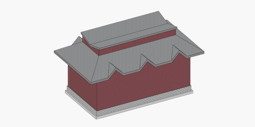
| 3. Split side boundary lines and add slope arrows to meet at desired distances. | 4. Roof pitches and overhangs can be further manipulated. |
Hip gable hybrid
Another example of using the cutoff level parameter is when you’re joining two roof types. In this case we have a hip roof and gable end roof hybrid. As in previous instances, prepare external walls on which the roof is going to be modeled. Make sure you have levels at the correct heights.
 |  |
| 1. Draw a roof with cutoff level at desired height. | 2. Draw a double pitch roof with base level at cutoff level. Attach gable end walls to roof and create side walls. |
3. Create dormer opening for the main roof by picking boundary lines of upper roof and side walls.
We’ve seen various roof types that can be created using the ‘Roof by Footprint’ tool in native Revit. Even more intricate details can be added to those roofs with Agacad Wood Framing or Metal Framing add-ins for Revit. We invite you to take a free trial.