The user interface of our Wood Framing CLT add-on for Revit is going to be enhanced within the next few weeks! The commands will be collected into a single ribbon and rearranged to make the workflow more intuitive and the UI overall easier to use.
This major new release is part of our ongoing quest to help optimize your work and reduce time spent on manual Revit tasks.
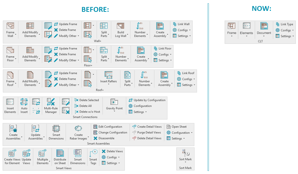
As you can see in the before-and-after image below, it was previously necessary to open separate Revit tools – like Wall+, Floor+, Roof+, Smart Connections, etc. – to access the functionality you needed.
With the new release, that is no longer the case. All functions are now available from a single compact ribbon, conveniently arranged according to the recommended workflow.
Let’s have a tour of the renewed ribbon.
The new ribbon & sub-menus
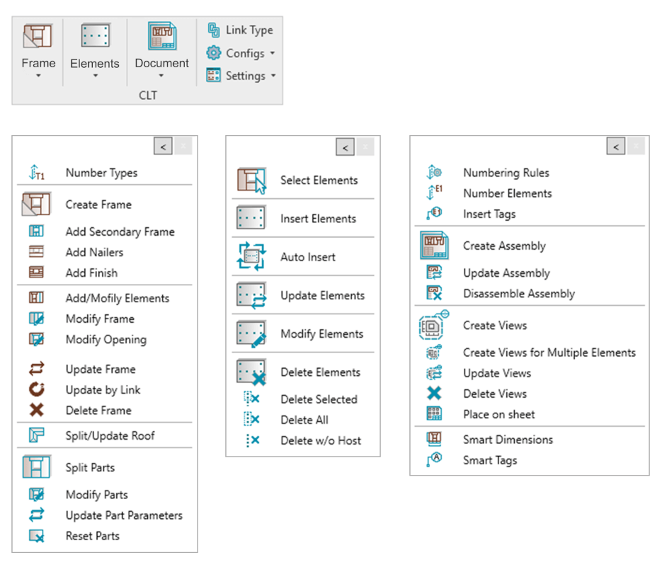
In the ribbon, there are six top-level functions: Frame, Elements, Document, Link, Configurations, and Settings. Here is what each of those is for.
Frame
Functionality needed for modeling frames with CLT panels
Elements
Functionality needed for creating connections common for CLT structures
Document
Functionality needed for numbering elements and creating shop drawings
Link Type
Use this to create links for walls, floors, and roofs.
Configs
Enter, create and modify all needed rules for modeling, numbering, dimensioning, etc.
Settings
Load all needed families for CLT Structures automatically, browse configuration files’ locations, and transfer element types and standards.
You’ll be able to open multiple floating tabs (containing commands for Frame, Elements, and Document) and minimize them to save working space, like so:
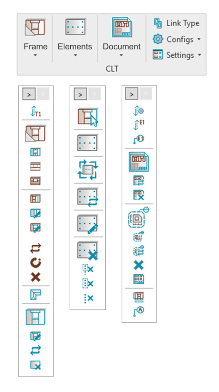
Frame tab
In the Frame tab, you have all the functionality needed for modeling: creating the layout/structure for the CLT panels and other framing elements or layers (like Secondary Frames, Nailers, as well as Splitting Parts to create CLT Panels or Sheathing and Paneling layers). There are also commands for modifying the structure after it has been created using the Frame command.
With the new interface, you’ll be able to Frame, Split Parts, and Modify the structure of Walls, Floors, and Roofs using the same commands; whereas in the old UI, you had to use Wall+ for Walls, Floor+ for Floors, etc.

Elements tab
In the Elements tab, you’ll find functionality needed for creating common CLT connections, such as dovetails, half laps, etc. You’ll be able to distribute them automatically using predefined custom rules based on your own standards, as well as modify them.

Document tab
In the Document tab, you‘ll find functionality needed for numbering elements and creating shop drawings based on your predefined rules:

Moreover, in the Numbering Rules window (which is called Elements Batch Numbering if you’re using our Sort Mark add-on), you‘ll be able to choose all needed rules for various categories (like Walls, Parts, Structural Framing, Structural Connections, etc.) and their parameters, which should be filled in, in a single configuration:
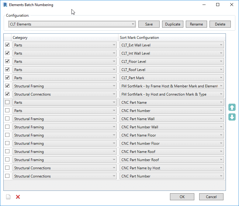
Then, after using Number Element, you‘ll just choose the configuration with all rules and Wood Framing CLT will automatically number all elements.
Link Type
In the Link Type window, you‘ll be able to create links for all elements walls, floors, and roofs in a single windnow.
Configs menu
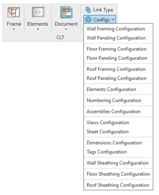
In the Configurations window, you‘ll be able to enter, create, and modify all needed rules for modeling, numbering, dimensioning, etc.
Settings menu
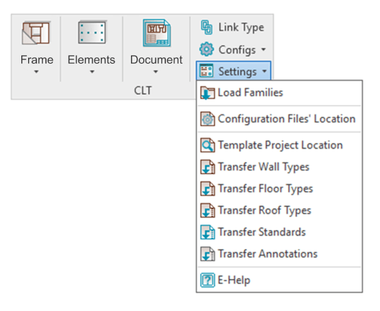
And finally, in the Settings window, you‘ll be able to automatically load all needed sample families – and your own custom families – for CLT structures, as well as browse the configuration file‘s locations and transfer element types and standards.
Design CLT at a whole new level
So, that’s an overview of the completely new software release of Wood Framing CLT. We’re confident it will help optimize your work and greatly reduce the time you have to spend on manual tasks.
Want to see how the workflow goes with your own eyes using the enhanced UI?
Join our free, live, CLT webinar on April 28, 2022!