Solutions
By sector
Light steel framing with full BIM benefits
Technologies that modern wood construction needs
BIM workflow for smooth design, fabrication and construction
By process
Full modern power for building design
Professional control and classification of building data
BIM's potential optimizing off-site work
Better handling of building resources
BIM's benefits for optimizing on-site work
Products
Be.Smart Building
Essential toolkit for enhanced productivity in Revit®
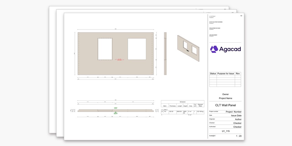
Efficient CLT-based building creation
Direct access to classification standards
Direct framing data export from Revit®
Integrated design and update of holes
Effective design of MEP supports
Ideal for modeling light-steel-framed constructions
Optimized packing and logistics organization in Revit®
Precast element design and documentation in Revit®
Full SIP system creation for any geometry
Synchronous Revit® family management
LOD 400 modeling automation in Revit®
Documenting Revit® projects at least twice as fast
Time-saving tools for Revit®
Advanced automation from design to construction
Be.Smart Manufacturing
Direct framing data export from Revit®
Optimized packing and logistics organization in Revit®
Boost your productivity in Autodesk® Inventor®
Be.Smart Infrastructure
Construction management & real-time tracking solution
Direct access to classification standards
Compare and control the construction work
Optimized production & efficiency on construction sites
Resources
All our articles and posts
Agacad's latest endeavors
Software updates and workflows
Upcoming and past webinars
Tutorials, documentation, expert tips and best practices
Our amazing clients share successes they have achieved
Insights into the state of BIM around the world – including some incredible projects
Our in-house professionals share their knowledge of the AEC industry