Want to frame walls, floors, and roofs quickly in Revit®? Our Wood Framing and Metal Framing BIM software for Revit streamline the framing process for architects, structural engineers, and framed building contractors and provide a wide range of options for modelling framed buildings.
The great thing about our framing software is that we’ve built best practices right into the tools, based on the insights of leading users. Those just starting out with our framing tools, however, sometimes feel overwhelmed doing the initial setup for a new project. That’s why we’ve pulled together these best practices, which will help even experienced users navigate more confidently from the start.
In this blog post, you’ll discover the essential steps for getting your project started on the right foot. We’ll start from the very beginning of the workflow so new users can start working on their own projects with confidence. And if you’re a seasoned user, knowing these steps will reinforce techniques with which you may already be familiar.
These essential steps – along with other useful recommendations – were also given in our recent webinar, so be sure to check that out below.
Modeling Recommendations
- The Wall/Floor/Roof structure should be layered the way the parts of the framing will be modeled, e.g.:
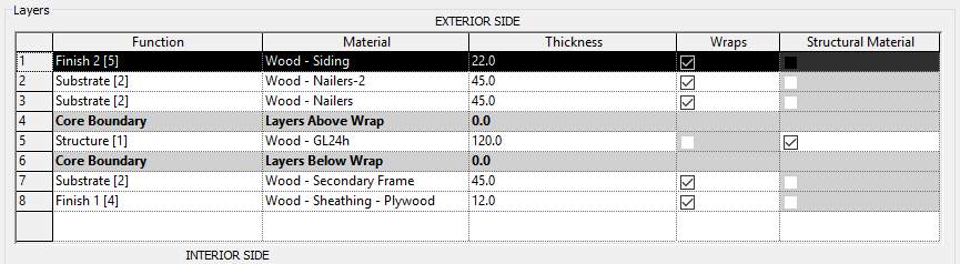
We recommend having only one ‘Structure [1]‘ layer inside the Core Boundaries. You should also assign a Material to each layer and if it has a Density parameter value, the element’s mass will be calculated. The thickness of these layers should be correct as well, and there are no limits to how many layers you can have.
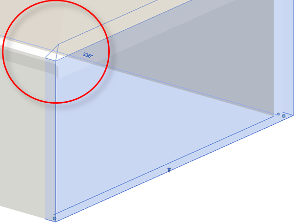
2. Avoid abnormal wall forms. Sometimes these occur when a wall is attached to a roof:
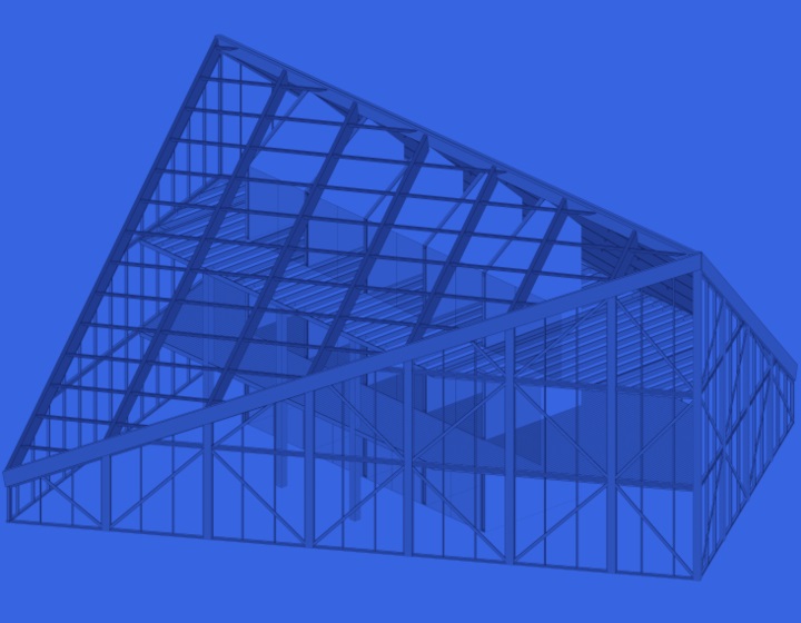
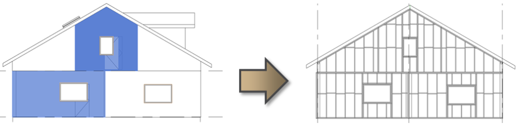
3. Walls/Floors/Roofs should be modeled, as they should be paneled and prefabricated:
Wall+/Floor+/Roof+ is capable of making frames for both on-site and modular framing. Splitting defines the modules of the wall/floor/roof. To define framing panels, the maximum height of studs, the maximum length of sidings, etc., you should split the wall/floor/roof where you want your framing to end.
Furthermore, you can split walls not only manually using Revit’s Split Element command, but also automatically using Smart Walls. Floors and Roofs can also be split automatically using Floor Panel Layout and Roof Panel Layout.
4. Pay attention to Wall Connections. I explain more about each of these 4 below.
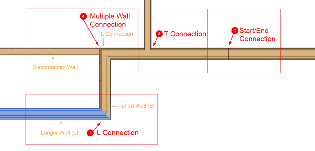
| L Connection | For L Connections, it’s important which wall is longer and which is shorter. Make sure they connect like they should be framed. In the image above, you can see that the selected wall is longer in this example. |
| Start/End Connection | Start/End Connections are created by splitting walls. |
| T Connection | T Connections are created by intersecting walls. |
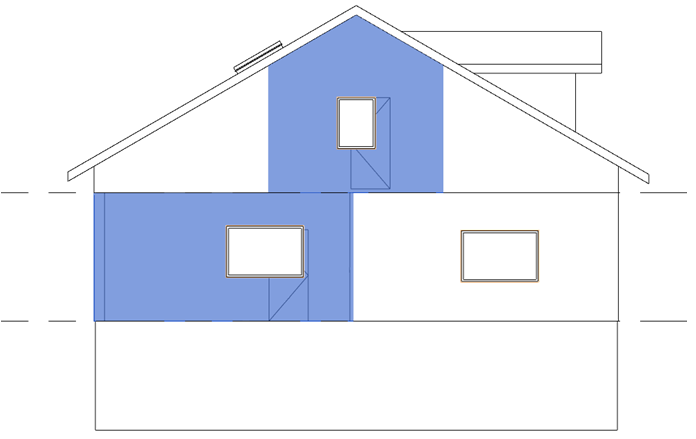
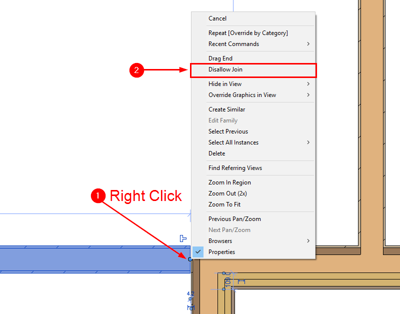
| Multi-Wall Connection | When multiple walls connect, we recommend disconnecting one of the walls (see image below) so that there would only be two walls connecting. In this example, I disconnected an interior wall, so two exterior walls will be framed as an L Connection. |
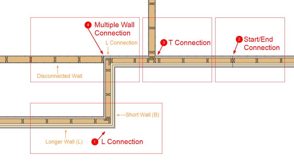
Result after the main frame is created:
For more on modeling recommendations, start at this point that we’ve bookmarked in our webinar.
Essential Steps Before Framing
After you’ve created the architectural model in Revit, you need to take a few simple steps before using our software to automate framing of the walls, floors, or roofs. In this blog post, we’ll focus on the most significant ones.
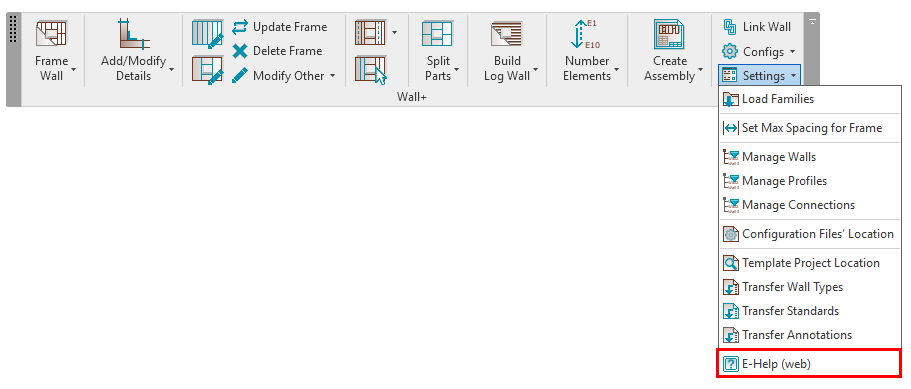
Before starting to work with our framing software, we highly recommend checking out the e-help pages. You’ll find a lot of useful information there, like technical documentation, sample projects, and recordings of webinars.
Now for those essential steps.
Load Families
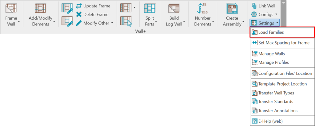
Choose the sample families to be loaded into the current project. Wall+ provides sample framing, detail, siding, and tag families, both Metric and Imperial, as well as sample schedules.
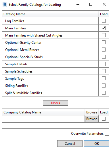
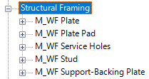
You can find the families in Project Browser → Families under Structural Framing, Structural Connections, Annotation Symbols and Generic Models categories., for example, here’s a list of families for loading Main Families:
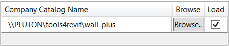
Alternatively, companies may have a path to company families, e.g.:
Locate Framing Configurations
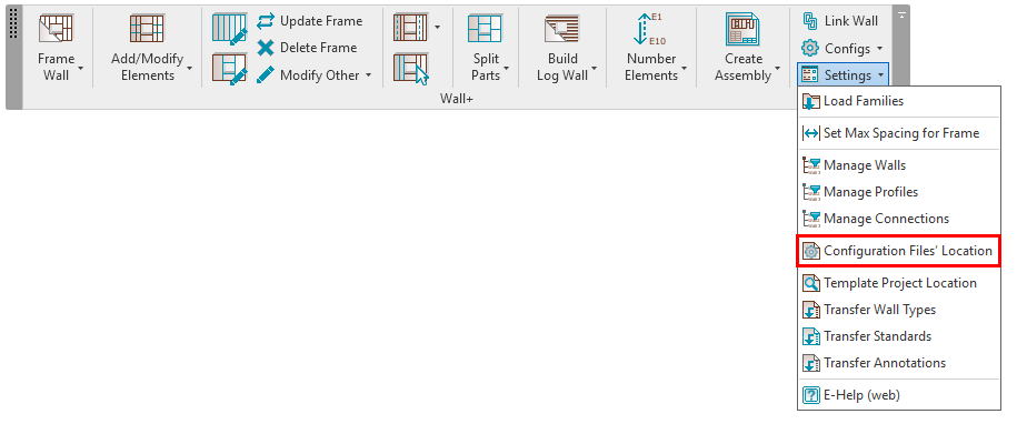
This is the location where your Configurations are saved. It could be your computer or somewhere on your company server.
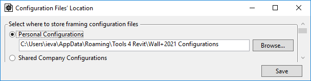
This path is written by default, so you don‘t actually need to do anything, but it‘s important to know where they are so that you could change the location if you need to.
Create Wall/Floor/Roof Link
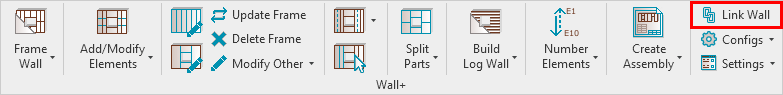
Link Wall makes a link between the wall type in the project and the configuration. Choose the wall type you want to link and apply framing configuration to the layers. See the numbers 1-3 and 1-7 below for a tour of the Link Wall configurations window.

1. All wall types from the current project. If you select a wall from the project, it will automatically be selected in this dialog so that you can quickly apply settings.
2. Information about selected type.
3. Information about selected wall layers where you can apply settings.
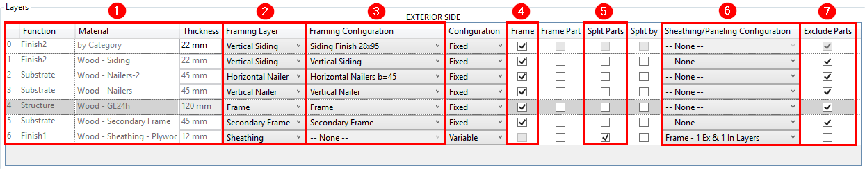
- Information from selected wall type.
Note: Material is mandatory for assigning framing configuration! - Framing Layer – select which framing layer has to be created.
Possible options: Frame, Secondary Frame, Vertical/Horizontal Nailers, Vertical/Horizontal Sidings, Wood Logs, Paneling, and two Sheathing layers. - Framing Configuration – select framing configuration with the definition of all framing parameters. There are default configurations that come with Wall+, but you can also create your own. To start out, we recommend trying out our sample configurations that are loaded together with the software.
- Frame – choose whether layers should be framed during the framing process or later.
- Split Parts – select if parts need to be split after using the Split Parts function or should be split later in the sheathing/paneling layers.
- Sheathing/Paneling Configuration – select sheathing/paneling configuration with definition of all sheathing/paneling parameters. There are default configurations that come with Wall+, but you can also create your own. To start out, we recommend trying out our sample configurations that come with the software.
- Exclude Parts – select the parts that need to be excluded from the wall. You can exclude parts from the project so that they will not be included in material takeoffs, schedules, and other lists or calculations. Do not tick this mark for layers where sheathing/paneling layers need to be created/split.
For more on these essential steps prior to framing, watch this section of our webinar:
Now that we’ve taken care of the essential pre-framing steps, we’ll move along into the rest of the workflow.
Automated Framing
After the model has been created, families loaded, and configurations mapped in the Wall/Floor/Roof Link, you can use the software to frame them automatically!
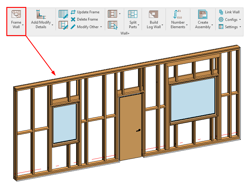
The software will distribute all Structural Framing elements to the main frame according to the settings created in your framing configurations. As mentioned, you can use our sample ones, duplicate them, modify them, and create your own.
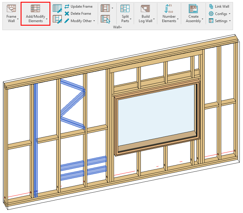
Modify Framing
Our software is very flexible when it comes to modifying frames. There are a lot of ways they can be modified depending on the situation and end result you’re looking for, so there’s no fit-all recipe. Just a lot of possibilities.
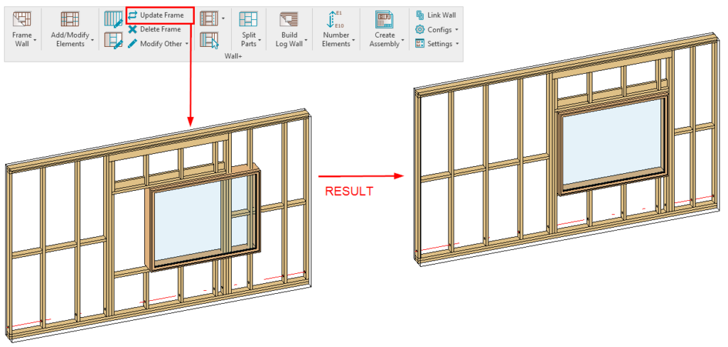
We can modify the architectural model and then update the frame; add diagonal, vertical and horizontal additional elements in specific locations, modify only instances of the frames without affecting the configurations; cut, delete, move, rotate elements; and much more.
For example, we can modify the architectural model and then, with only one click, we can update the frame:
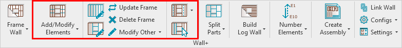
We can also add various layouts of additional vertical, horizontal, and diagonal elements in specific locations:
In this webinar, I showed and explained a few of the most commonly used features for modifying frames. Of course, there are a lot more, and you can see of them by watching here in the associated webinar:
Framing Additional Layers & Adding Details
After the main frame has been created, it’s time to frame other layers in Walls/Floors/Roofs, like Secondary Frames, Nailers, and Sidings. You can also split parts for Sheathing and Paneling layers…

…and even distribute Structural Connection elements automatically:

For more on framing layers and auto-distributing hardware, start here in that webinar recording:
Numbering

After modeling is complete but before moving on to shop drawings, you need to Number the Elements. Of course, with our software you can do that automatically as shown at this bookmark in the webinar:
Creating Shop Drawings
Once you’ve numbered all elements in the project, you’re ready for the last step: creating shop drawings.
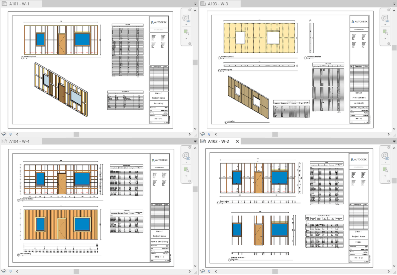
In this webinar, I also demonstrated the process of transferring the project standards from our sample project (you can transfer them from your own template as well) to make the process even faster and smoother:
So that’s a look at our steps for framing successfully in Revit using our Wood & Metal Framing tools. We hope they prove useful in your framing endeavors!