AEC professionals in the light-gauge steel (LGS) framing industry face constant pressure to churn out deliverables, like drawings and schedules. Modeling and updating a frame in Revit manually, however, means hours of additional work.
Not to mention the high probability of errors. And mistakes at the design stage result in wasted resources, increasing the carbon footprint of the building project.
Enter AGACAD’s Metal Framing add-ons for Revit. They help fabricators and framed building designers quickly and accurately create, update, and manage LGS framing drawings and schedules by automating Revit tasks.


Increased productivity and fewer mistakes during the building design phase lead to time savings, money savings, and substantially less waste. And less stress, too.
Features & benefits
Here‘s a quick look at the key benefits of Metal Framing functionality, which saves you time and money and reduces building waste.
Light metal framing workflow
The following 3 stages apply to framing walls, floors, and roofs.
Just to give a little background. In order to proceed with the standard workflow (i.e. from Frame Walls to Shop Drawings and CNC Data), it’s first necessary to load families. Without loading families, it’s impossible to use our Revit add-ons. Then, you need to link walls (or floors or roofs) with the configurations. Without doing so, it’s impossible to frame them because no configurations would be linked, and our add-on wouldn’t know in which walls/floors/roofs – and in which layers of them – to fill with the loaded families.
So, without further ado, here are those 3 stages, followed by the standard workflow.
Stage 1: Load Families and Sample Schedules which come with the add-on.
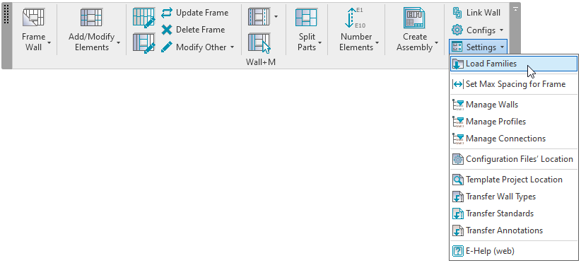
Choose to load main families like studs, plates, service holes; detail elements such as bolts, angles, clips; sample schedules with pre-defined fields, filters and sorting.
Stage 2: Create links between your building element type layers and configurations.
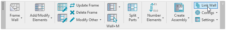
Read more about Link Wall settings here.
Stage 3: Proceed with the workflow outlined below.
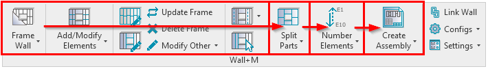
Firstly, start with Framing your building elements. Then continue with splitting parts for sheathing or paneling layouts. Once framing and parts are ready, make sure to number all your elements for assembly schedules and CNC export.
Find out more about the workflow in our Getting Started Video page.
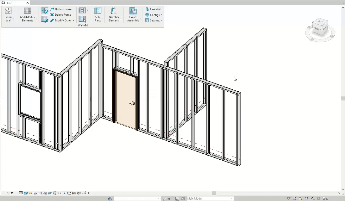
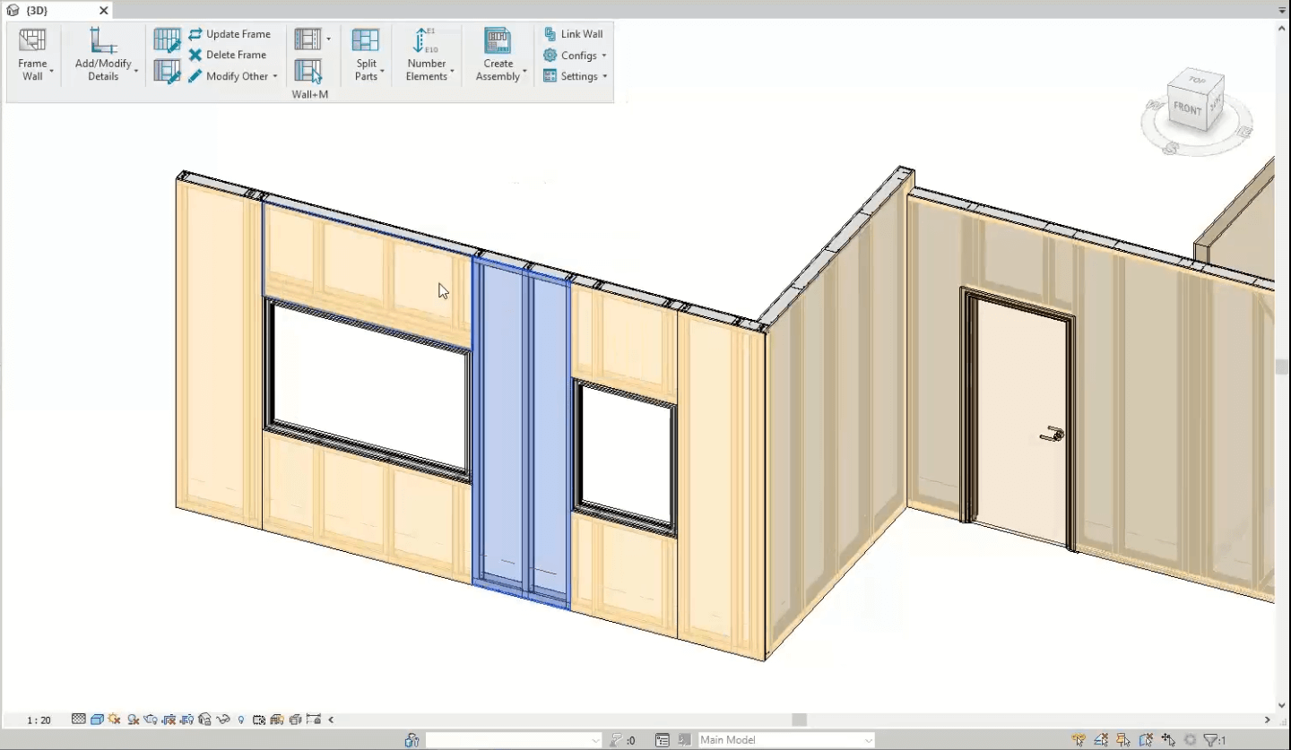
Frame your buildings with just ONE click
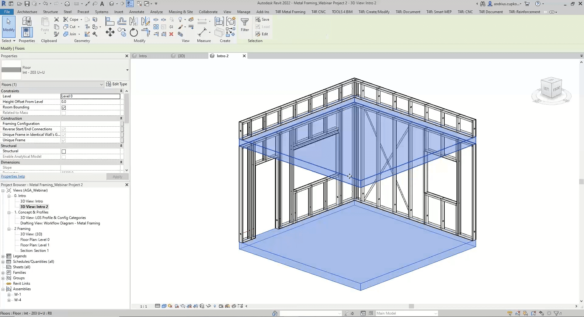
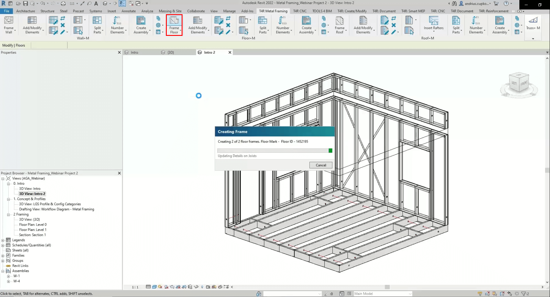
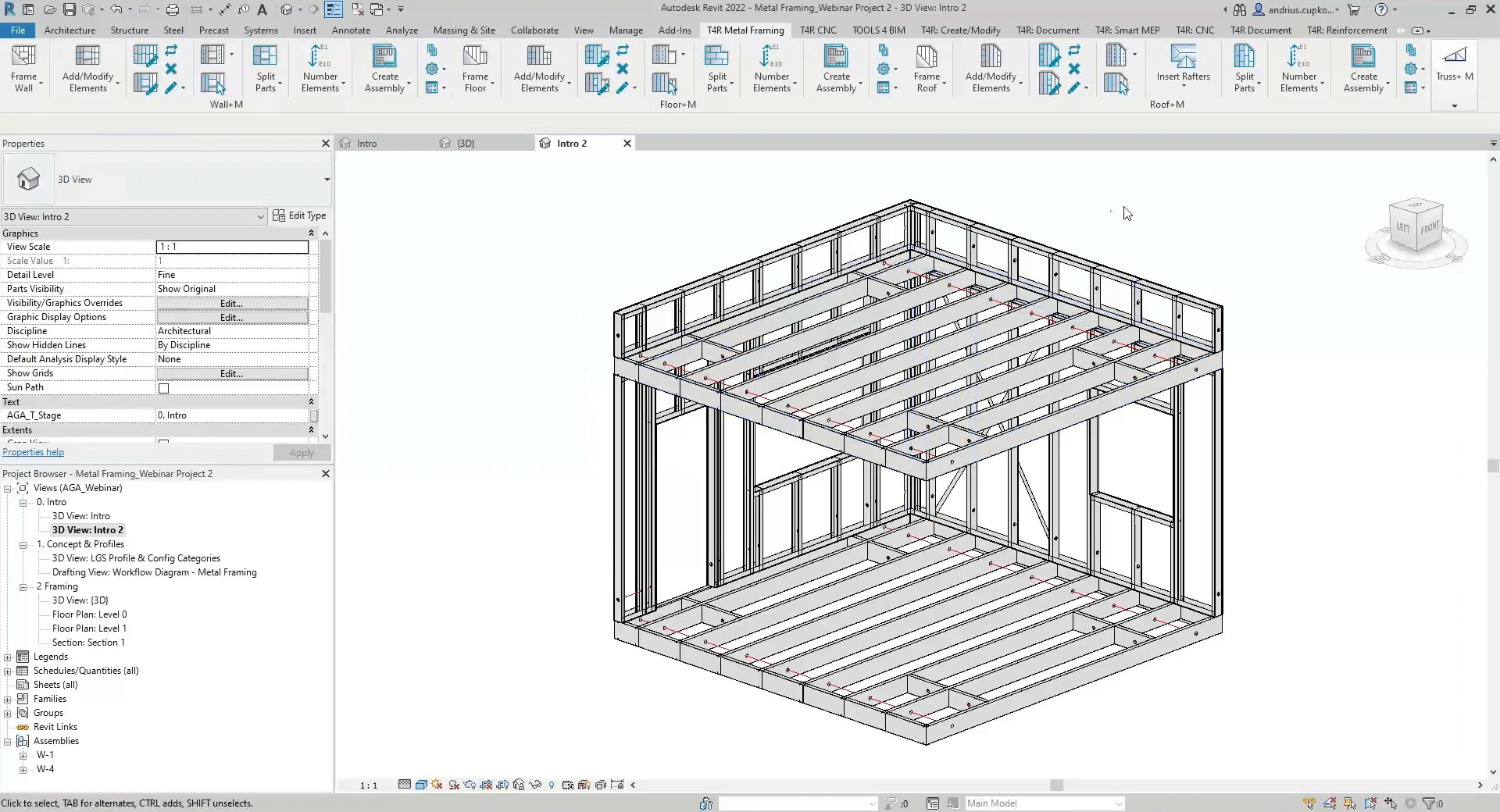
Once families are loaded and element type layers are linked, you can start framing your building automatically. Just click Frame Wall (or Floor or Roof, depending on what you‘re framing) and the add-on will do the job in seconds.
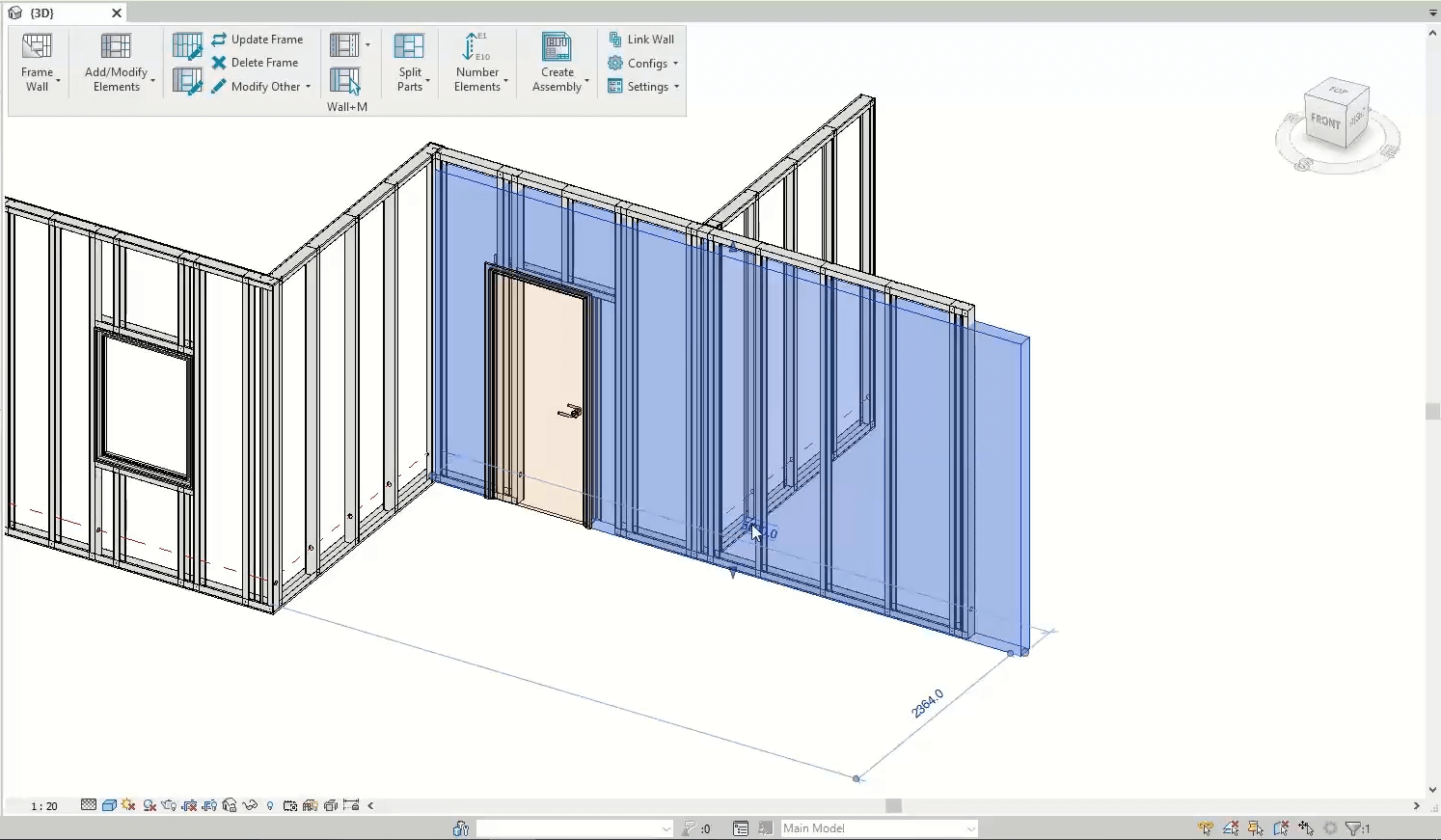
Update any changes automatically
If your framing host shape changes, or you decide to modify your configurations, you can easily and quickly adapt changes to your frame.
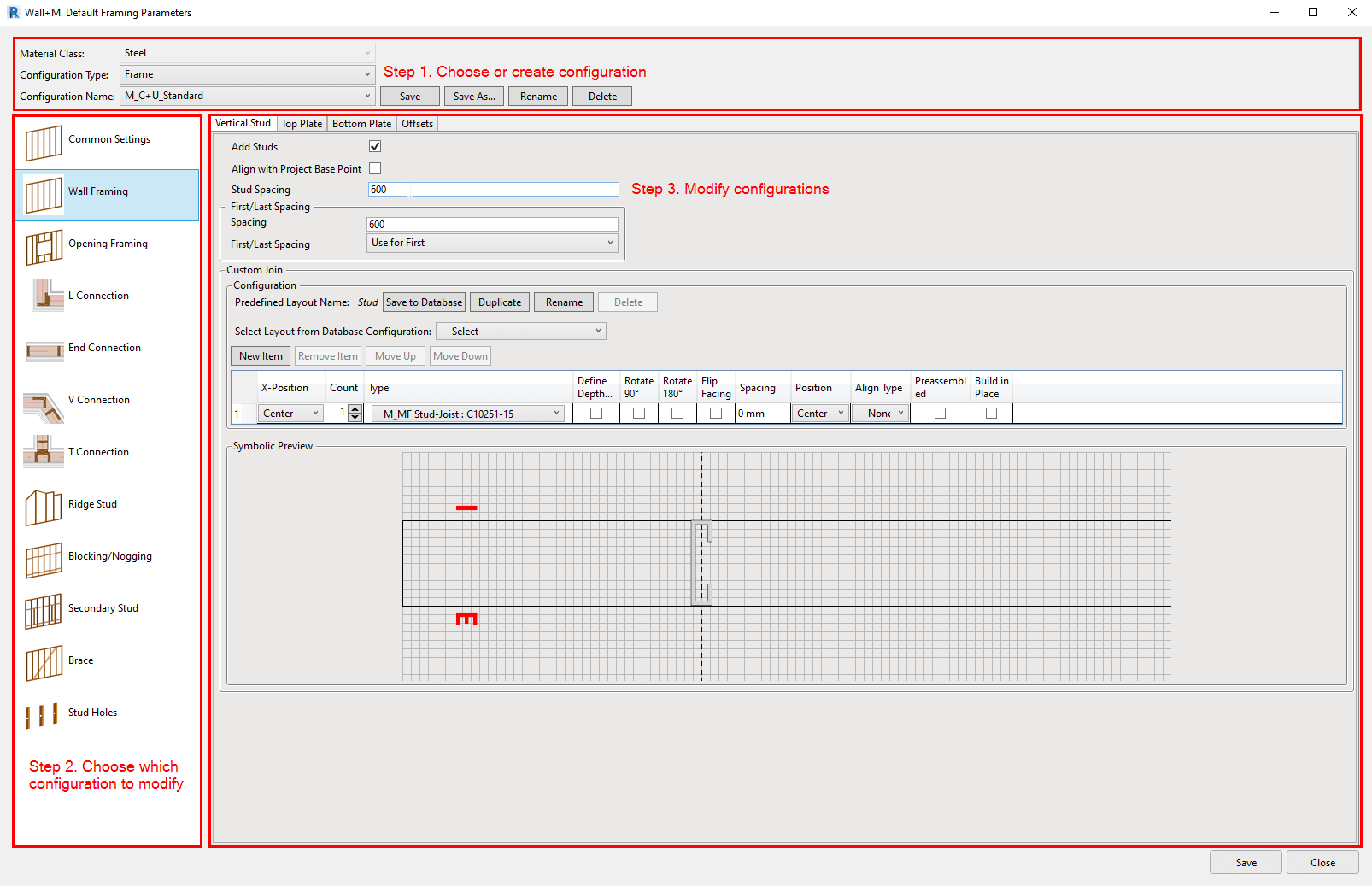
Create automation rules
Automation rules, also known as configurations, can be defined for framing, sheathing or paneling, element numbering, and shop drawings. You can read more about all configurations in our technical documentation page.
The image below represents Framing Configurations dialog layout and workflow.
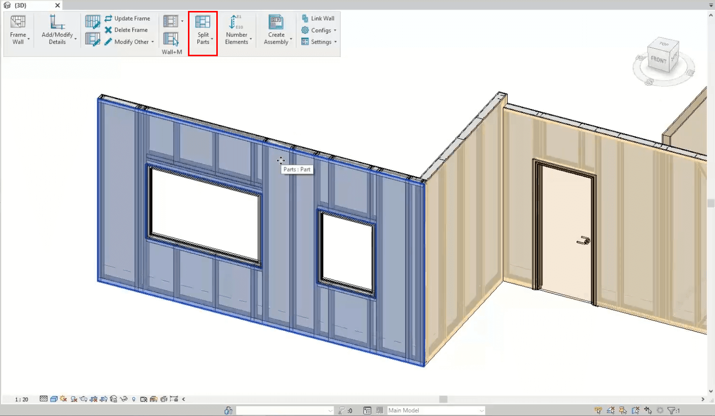
Split Parts to Create Sheathing or Paneling Layouts
Create rules for your own OSB or Gypsum Wallboard sheathing as well as insulation or venitlated facade panel layouts using Sheathing or Paneling configurations, respectively.
Number elements
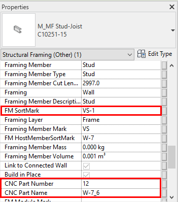
The last step before assembly creation involves the numbering of walls, framing elements, and parts.
In the screenshot below, the highlighted parameter values of a vertical stud were filled using numbering rules defined in Numbering Configurations. For example, the FM SortMark parameter value will be visible in framing element tags on assembly views.
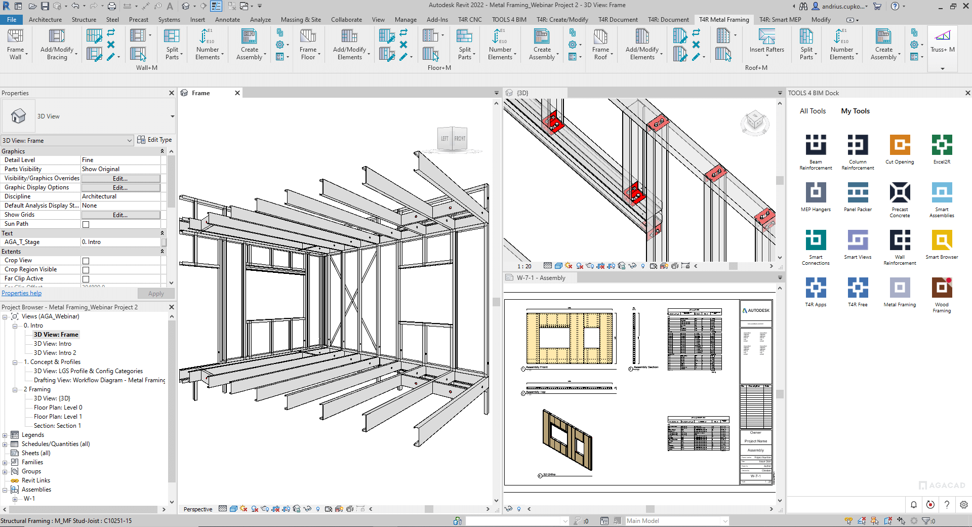
Automate shop drawings
You can now create frame assemblies and shop drawings with just the click of a button. Sheets with automatically dimensioned and tagged views as well as schedules will be generated using Drawing Configurations and your own sheet layout templates.

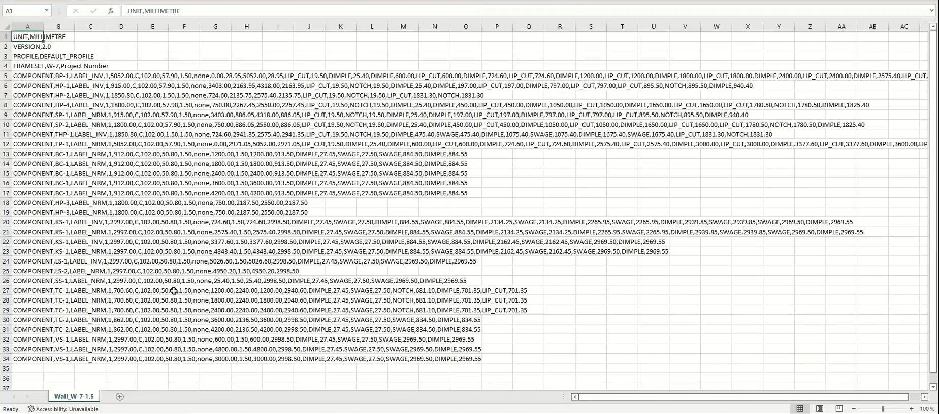
Export framed Revit model data to CNC machines
Use a CNC Metal Exporter add-on to do this. Pick the machine type from the available options and generate the .csv format file using pre-defined settings.
In sum
That’s the workflow to follow for framing with light-gauge steel in Revit using our Metal Framing Wall, Metal Framing Floor, and Metal Framing Roof add-ons.
We hope current users find this overview useful. And for those of you who aren’t users (yet!), we invite you to request a free demonstration with our engineer, try out our plug-ins for free, and see what a difference they can make in your daily work.
Free Demo
Before you take a trial of one of our Metal Framing add-ons, we encourage you to get a free personal demo with our BIM application engineer. That way, you’ll go into your trial period with a better idea of how to use it and already have answers to your preliminary questions.
Free Trial
To start a free trial of Metal Framing Wall, Metal Framing Floor, or Metal Framing Roof, download our TOOLS4BIM Dock for your Revit version.