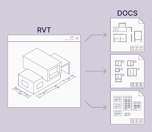
AGACAD has a brand-new tool available that makes project documentation easier for architects, MEP engineers, and structural engineers who use Autodesk® Revit®. Our newest product – Smart Views – lets you create any number of views with automated dimensions for selected elements in Revit without creating an assembly.
Smart Views is especially suited for Revit users who need to make drawings of sections and elevations of any building element, all the way from preliminary design stages through to a detailed design. It could be for a cast-in-place concrete wall with MEP openings or just a casework, a wood-framed wall or window, an elevation of selected walls, or a section of a particular connection.
So whether you’re an architect, structural engineer, or HVAC engineer, Smart Views is here to make your documentation tasks in Revit easier. And faster. That’s why we made the tool: to remove some stress out of your daily work.
Great news for current users!
If you are a current user of our Precast Concrete, Wood Framing, or Metal Framing design software, we have included Smart Views in your existing license(s), free of charge! See the ACTIVATION INSTRUCTIONS.
Not a current user of AGACAD’s Revit and BIM tools? We warmly invite you to out Smart Views for free – please scroll down for instructions.
A Quick Tour of Smart Views
Here’s a brief intro as to what you can accomplish with Smart Views.
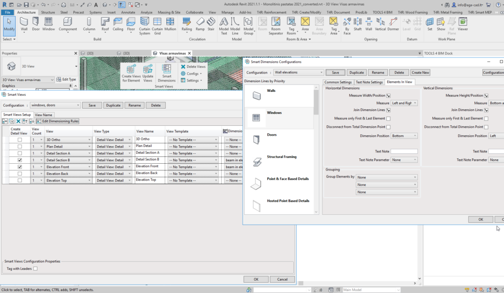
A familiar Revit app user-interface
Smart Views sports AGACAD’s consistent UI for views, templates, tagging, and dimensioning configurations.
In the example below, I selected two walls, and then Smart Views automatically created model views with dimensions according to the configurations I had set.
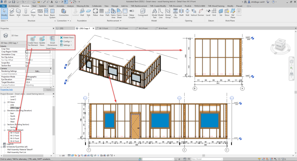
Make views by selected elements
Smart Views will automatically crop views and align them with the respective elements. And so that you don‘t need to create anything new, you can use Revit’s standard Dimension, Text Types, and View Templates. Just use whatever is available in Revit or what you have already been using as your company standard.
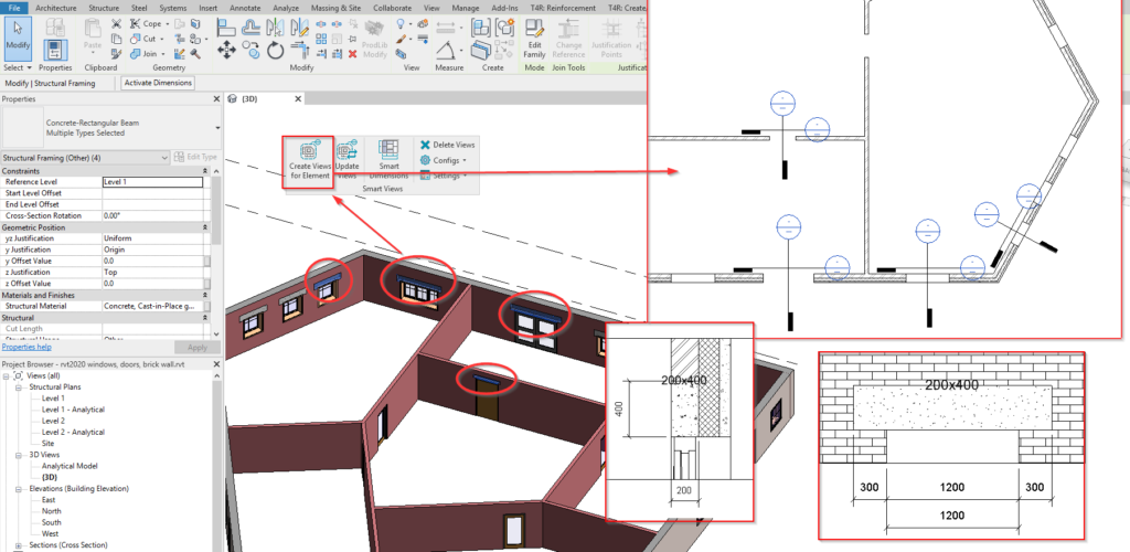
In the example below, I selected a couple of beams above doors and windows, and I set the configuration to generate section and front views. Voila! Views with the correct orientation and the desired dimensions!
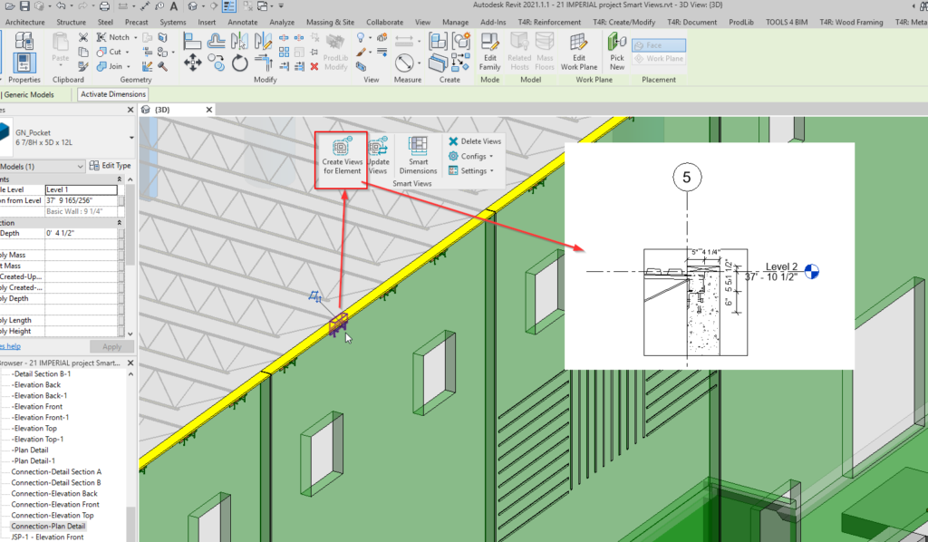
Here’s another example. In this one, I selected the support element for a steel joist, and I get a detail view of it:
Dimension any view of a Revit element
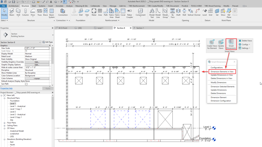
Besides making views for selected elements, you have the option to automatically place dimensions in any section, plan, elevation, or callout views.
In the example below, I went to a tilt-up wall’s elevation and clicked ‘Dimension Elements in View’ for my configuration. All dimensions seen here were created automatically:
So that is a brief introduction to the newest Smart BIM tool that we’ve added to our portfolio. We invite you to take a free trial.


