Wood framing floor software for modeling timber floor panels, joists & details in Revit®

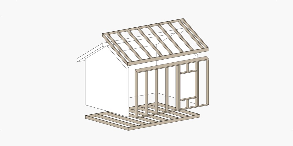
Wood Framing Floor makes framing timber floors fast and easy with real-time full project updates in Revit®. Whether you need to frame multi-layer floors, trussed floors, or panels for prefabrication, this BIM Solution for Revit can do the job. Plus it generates views with automatic dimensions for floor panels or segments as well as accurate bills of materials and shop drawings. So quality production and accurate assembly on site are ensured.

      Compatible with Autodesk® Revit® 2023, 2022, 2021

Connectors, cuts, supports, and other details can be distributed based on predefined rules or connection types. They can then be modified or updated to suit the project design stage and the level of detail required. Floor frames and the layout of frame elements and details can be modified and updated whenever the project is changed. Dynamic update functionality can make changes to all floor frames of the same type at once.

Floor frame elements in the project can be easily marked based on their properties and locations in the floor structure layer. And information for fabrication can be automatically generated with all desired views, schedules, and drawings for each floor segment or panel.

POWERFUL FEATURES

Floor+

TIMBER FLOOR FRAMING

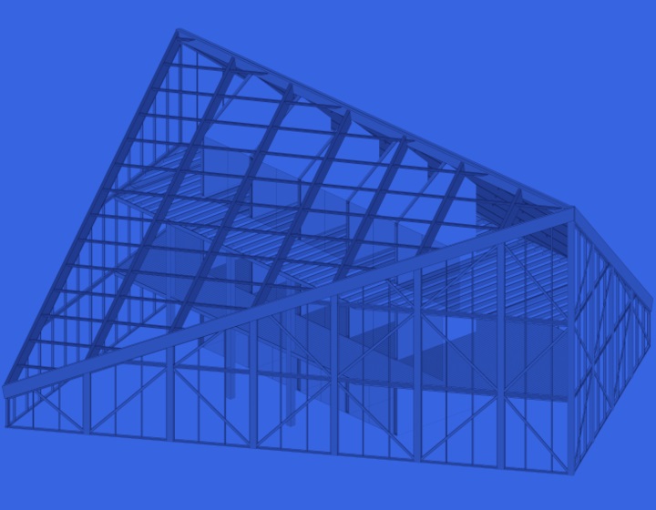
Automate wood framing of floors in Revit® projects using Wood Framing Floor+. It helps you make better decisions, move much faster and avoid errors at every BIM stage – from design and documentation to segment fabrication and construction.

  • Auto-generate detailed multilayer floor framing for your Revit model using predefined or custom rules and templates.
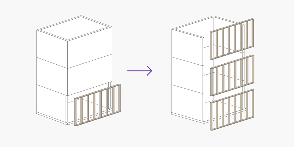
  • Frame multi-story houses 10 times faster than using standard Revit interface.
  • Easily control supporting structure, including battens and flooring; distribute details, service holes and more.
  • Automate sheathing layouts.
  • Freely revise your Revit model by easily selecting the elements and properties you want to modify.
  • Find structural and engineering clashes; cut and frame openings according to predefined rules.
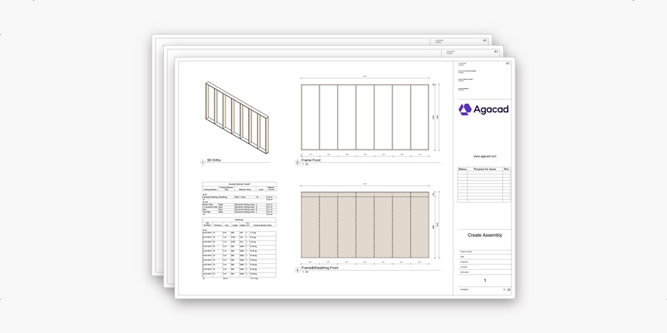
  • Easily prepare shop drawings and cut lists, with all required views, where elements are dimensioned, sorted, tagged, scheduled, and mass calculated.
  • Optional export to any CNC machines and CAD/CAM production lines, such as WEINMANN, Randek, etc.
  • Floor frames update and adapt according to any changes.
  • Perform structural analyses without leaving Revit, or export your wood frames to external analysis software at any stage of design process.

Floor Panel Layout

PREFABRICATED FLOOR PANELING

Take the architect’s designed floor and automate panel layout planning. The software Floor Panel Layout draws symbolic lines to indicate the future panels according to predefined rules. Then it creates real Revit® floor panels.

  • Panel Layout Planning includes functions for better understanding how the floor will be divided. You can control every division line and automate the division process by predefined rules.
  • From the beginning, the architect’s designed floor can be divided into coarse partitions, or Regions. Regions can be created automatically by using Floor edges and supports (split lines), and also by Generic or System Openings with predefined distances.
  • Regions can be divided into Panels by predefined spacing.
  • Panels can be aligned, modified by selected floor face, and additionally split.
  • Various automated splitting functions facilitate the process: split the panels in half, by maximum spacing, by middle to both ends, in middle and to both ends, from first selected, or from both ends.
  • Join selected Regions or Panels, if needed.
  • Create individual panels for the selected floor face or for the whole floor.
  • These entire floor Panels can later be moved into the new phase through its Properties for better filtering and scheduling.

Truss+

FLOOR TRUSS FRAMING IN REVIT®

Create wood truss systems with analytical lines instantly, and auto-generate shop drawings tailored to your standards. Functions are versatile, parameters are easy to control, and changes occur in real time.

  • Build full truss systems in one go with the configurable 3D grid (escaping the limited and time-consuming nature of standard Revit truss family insertion).
  • Easily assess options – such as wooden truss framing – in economic, structural or systemic terms, to make the best decisions.
  • Create new parametric uniquely shaped truss families based on model lines and roofs for immediate use in your projects.
  • Freely revise your Revit model; update and adapt truss systems.
  • Get real-time take-offs and views, automatic creation of shop drawings and cut lists, and easy export to CNC machines.

Cut Opening

PRECISION OPENINGS FOR MEP SERVICES AND BUILDING STRUCTURES

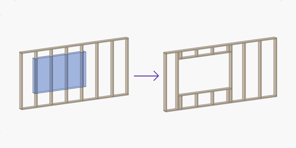
Automatically create openings throughout a Revit® model where ducts, pipes, cable trays and conduits intersect with walls, floors, roofs, ceilings, beams and columns. Cut Opening creates openings with special holding details for structural beams.

  • Add openings with predefined sizes in accordance with MEP line based element sizes, categories and system classifications.
  • Automatically join openings with predefined configurations.
  • Automatically insert Fire Dampers where ducts clash with walls, floors, ceilings or roofs with fire rating.
  • Automatically insert structural openings for separated architectural and structural models.
  • Enhance BIM-team work and deliverables for integrated project delivery (IPD).

Sort Mark

FLEXIBLE ELEMENT AND GRID RENUMBERING

Renumber Revit® elements just the way you want, detect and renumber grids, determine swing direction and orientation (and add them as properties), recalculate shared coordinates, and much more.

  • Detects grid geometry and renumbers them.
  • Renumbers grids automatically after they have been changed in the project.
  • Powerful and flexible functions allow renumbering of any Revit elements (Doors, Windows, Beams, Columns, Pipes, etc.) in a number of different ways.
  • Writes swing direction for the doors into the door’s properties.
  • Writes flip/mirror orientation for the selected elements.
  • Recalculates shared X, Y, Z coordinates.
  • Creates new shared parameters and many more functions.
  • Possibility to save numbering settings under the separate name.
  • Possibility to sort elements in Ascending/Descending order.

Smart Views

MAKING VIEWS & PLACING DIMENSIONS FAST IN REVIT®

Get sections and elevation drawings for any building element easily using functions that create views and dimensions for selected elements quickly.

  • Uses configurations instead of manual work
  • Crops views to the element size
  • Creates automatic dimensions based on defined configurations
  • Applies view templates to all new views
  • Creates the number of views you set in the configurations for multiple selected elements
  • Renames views based on configurations
  • Apply dimensioning rules to any Revit view or selected elements in view

Want to find out if this is the right solution for you? Our professionals can help you quickly find out how this software will benefit your design process.

FRAME YOUR PROJECT!

Don’t waste time reading technical documentation, and see that this is the solution for you! Our Expert will frame a part of your project, demonstrate software functionality, and share best practices and the most efficient way of framing, taking into account your current needs.

Duration: 2 hour. Cost: 280$/280€

You’ll leave the demonstration with:

– Part of your project already framed;
– Your questions answered;
– 30-day software trial;
– Support during the trial period.


CLIENT STORIES

Developed in compliance with standards and guidelines:

Eurocode 5: Design of timber structures – Part 1-1: General – Common rules and rules for buildings (EN 1995-1-1:2004: E)
Standards Australia AS 1684.2-2010 Residential timber-framed construction
Standards Australia AS 1720.1-2010 Timber structures – Design methods
New Zealand Standard ZS 3604:2011 / Timber Framed Buildings
CWC (Canadian Wood Council) Wood Design Manual including CSA O86 Standard and CWC Commentary on CSA O86 (2010).
National Design Specification® (NDS®) for Wood Construction (NDS 2015). American Forest and Paper Association (AF&PA). American Wood Council, Washington DC, 2015.
The Encyclopedia of Trusses. Alpine Engineered Products, Inc., 2003.
Truss Design Procedures and Specifications for Light Metal Plate Connected Wood Trusses / TPIC – 2014. Truss Plate Institute of Canada (TPIC), 2014.
Using Narrow Pieces of Wood Structural Panel Sheathing in Wood Shear Walls. American Plywood Association (APA), The Engineered Wood Association, Tacoma, Washington, 2005.

PRODUCT BROCHURES

Learn more about the AGACAD products by reading our selected brochures.

Videos

Testimonials

Panel Designer at Deltec Homes, Inc., USA

“My colleagues and I are very happy with the much-improved quality of the shop drawings I’m able to produce with Wood Framing Wall. I’m now working directly from the same model we generate all our plans from, so the potential for error is much reduced. I also now have control over my deliverables for the shop: I can include a lot more information than before, and I can exclude unnecessary information that used to clutter up panel sheets. One example of major improvements is that sheathing used to be just listed in a table, now it’s all drawn out graphically and easy to understand, which reduces the chance the shop could make a mistake.”

Related products

Metal Framing Floor
Metal Framing Roof
Wood Framing SIPS
Smart Views

Recommended products

Smart Browser Free
Wood Framing Roof
Wood Framing Wall
Smart Browser
Smart Connections
Panel Packer