During the past year we implemented over 40 updates to our Wood Framing and Metal Framing BIM software for designing walls, floors, and roofs of prefabricated timber and light-gauge steel framed buildings in Revit®. Enumerated below are the top 31 enhancements (it was hard to choose!) that were made from February of 2019 to February of 2020.
These updates include new features and requests made by clients. (Click a topic to scroll down for details.)
Framing updates (Feb 2019 – Feb 2020):
- Align Stud Spacing with Frame and Opening Sides
- Split Sheathing by Openings and Prioritize Merging
- Expanded Possibilities for Joined Openings
- New Options in Link Wall/Floor/Roof
- Split Studs by Brace
- Multi-frame Assemblies
- New User Interface
- Framing Reports & Suggestions
- Validate Walls
- Custom Studs/Joists, Top Covers, Top Plates, Blockings/Noggings, Bottom Plates and Bottom Pads
- Custom Ridge Studs and Edge Joists
- Variable Joists
- Manage Connections
- Splitting Parts using Special Rules
- Modify Sheathing/Paneling
- New Numbering Technology
- Generate and Modify 3D Grids Created by One Roof Line
- Generate Trusses by 3D Grids and Auto-Array throughout a Roof
- Complex Truss Roof Framing
- Create Uniquely Shaped, Parametric Truss Families even for Multiple Roofs
- Modify Trusses using the Truss Builder
- Terminal Truss Roof
- Replacing Trusses
- Overhang Framing
- Create separate preassemblies for each joined opening
- Add transportation braces (even across openings)
- Align Secondary Stud System with Project Base Point
- More options for brace groups
- Special layouts and splitting options for paneling
- Minimum dimensions for openings to be framed
- Toggle configuration visibility
1. Align Stud Spacing with Frame and Opening Sides
We began 2019 with an important improvement for aligning studs and joists allowing you to distribute studs and joists by a predefined spacing and restart the spacing at king studs or at the sides of openings.
In the UI screenshot below, you can see this new feature in green: Align Stud Spacings with Frame and Openings Sides. Options in the dropdown menu let you align spacing with Opening right side, Right king-left side, or Right king-axis.

Example: Studs (or joists) are aligned with the right side of the opening (Opening right side):

Example: Studs (or joists) are aligned with the left side of the right king (Right king-left side):

Example: Studs (or joists) are aligned with the axis of the right king (Right king-axis):

This update was made to Wood Framing Wall, Floor, and Roof as well as Metal Framing Wall, Floor, and Roof.
Read more about aligning and spacing studs in our blog post.
2. Split Sheathing by Openings and Prioritize Merging
This feature pertains to sheathing and paneling, allowing you to split them by openings and to prioritize merging in the horizontal and vertical directions — while keeping everything aligned with the studs!
Here’s an example. Let’s predefine the sheathing dimensions to 3000 x 1200 mm, split the sheathing vertically, add horizontal splits and vertical splits on the nearest opening studs, and set to horizontal prioritization for merging:

Below, the above settings are applied to two different walls:


Read more about splitting sheathing and prioritizing merging in our blog post.
3. Expanded Possibilities with Joined Openings
Need to frame joined openings in Revit? This feature lets you create custom trimmers for left, middle, right, and center locations and exercise more control over top and bottom cripples:

Control Left, Right, Center and Middle Trimmers using custom variations:

Use king studs and headers by full-opening width configuration:

Read more about this Joined Openings update in our blog post when it came out.
WATCH this 3-min webinar clip about Joined Openings [YouTube]
4. New Options in Link Wall/Floor/Roof
New options were added for linking walls, floors, and roofs.

The selected configuration may be FIXED during the framing process or VARIABLE and selected while framing is in process.
If you set the configuration to be VARIABLE, then you can select any framing configuration from the list while you are framing:

5. Split Studs by Brace
This feature made it possible to run a diagonal brace through studs, essentially dividing them into separate stud groups.

6. Multi-frame Assemblies
This new feature lets you create assemblies of multiple frames in Revit. To use it, first click ‘Add Frames or Assemblies to Assembly’, select an assembly that has already been created, and then select multiple frames or assemblies that you want to add. After the selection is finished, you need to end the task by clicking ‘Finish’ at the top-left of the Revit window:

Then, update the assembly, and all elements in multiple walls will be tagged, dimensioned, calculated, etc.

7. New User Interface
The user interface of our software for framing wood and metal walls, floors, and roofs in Revit got a makeover in July 2019. All previous functions were retained. The re-arranged locations and complementary icons for Wall+, Floor+, and Roof+ can be seen in the Old UI vs. New UI screenshots below. Tool-tips were also added to describe what a command does simply by hovering over its icon.


Exploded view of WALL functions

Exploded view of FLOOR functions

Exploded view of ROOF functions

8. Framing Reports & Suggestions
After selecting walls or floors and using the ‘Frame Wall/Floor/Roof’ command, the tool automatically generates a report letting you know how many walls/floors/roofs were checked, how many and what kind of issues were found, and provides suggestions for resolving the issues:

9. Validate Walls
This feature checks whether the walls in the current project fit the predefined settings. Only validated walls should be framed.
In the example below, a project containing five walls was checked, and Wall+ found that one wall did not have a material assigned to its layer(s). In the Validation/Layers Report, we can see the Wall Type, Id number, and the ‘Message’ informing us of the issue:

10. Custom Studs/Joists, Top Covers, Top Plates, Blocking/Nogging, Bottom Plates and Bottom Pads
This feature lets you create custom studs and joists, top covers, top plates, blocking/nogging, bottom plates and bottom pads.

Framing members will be distributed based on your own configuration that can be saved in the database for future use.
Here are two examples using Wall+ that show common ways double-element studs are placed using this new function. You can also do this with joists in Floor+ and Roof+.
First, here are back-to-back studs.

Zooming in a bit…

And in the second example we have some side-by-side studs.

Closer up…

11. Custom Ridge Studs and Edge Joists
This update made it possible to customize ridge studs and edge joists just like you can with common studs and joists.

12. Variable Joists
A new sample family was added to Wood Framing ROOF that allows you to create sloped joists for roofs with variable layers.

WATCH how to use sloped joists in this 2-min clip from our webinar! [YouTube]
13. Manage Connections
In the past it was already possible to manage profiles of structural framing elements. But this update made it possible to manage connections using the Manage Connections command.

In the ‘Modify Elements – Structural Connections’ window, you can browse through distributed structural connection families, choose parameters for review, modify their values, etc.:

WATCH how to manage connections in this 2-min clip from our webinar! [YouTube]
14. Splitting Parts using Special Rules
New rules were created in part splitting that allow you to select different splitting types, configure slitting around windows, doors or other openings, etc.

Upper row – regular panel splitting
Lower row – panels split per predefined distances around the windows and doors.

15. Modify Sheathing/Paneling

An option was added to modify the selected wall/floor/roof layer sheathing/paneling per custom settings if you need to make unique changes. All configuration settings are the same as in the Sheathing/Paneling Configuration.

16. New Numbering Technology
This update lets you set your numbering configurations and then number all elements with one click. It has many options for simple and complex numbering when you need to load many numbering rules. Here you can number wall/floor/roof segments, parts, framings, and connections.

Read more on numbering in our Wood Framing Wall e-help.
17. Generate and Modify 3D Grids Created by One Roof Line
The Truss Builder in our Wood Framing design software lets you build full, complex truss systems at once with the configurable 3D grid, skipping the limited and time-consuming standard process of inserting Revit truss families.
This update to our truss framing tool makes working with 3D grids much easier. In the past you would have to select multiple symbolic model lines in order to generate the 3D grid, but now if you use the “Pick Walls“ command to create the roof you can generate the grid by selecting only the roof and one symbolic line.


Here’s how to do it.
First click “Insert Truss System Grid by one Roof Line”, then select the roof, the symbolic line, and choose a System Grid Type:


All pitches, overhangs, setback, and other values are adjusted automatically, so you don‘t have to calculate anything.
Once the grid has been generated, it can be modified simply by changing the “Instance parameters”. (In the past this could only be done by using the “Modify Truss System Grid” function.)
In the example below, the “Set Main Roof” is unticked so that the valley set grid for this system could be inserted later. In this example, 3 plies were added for the girder:

Finally, I selected the grid and generated the valley set grid:

I used the same “Insert Truss System Grid by one Roof Line” function to generate other grids in this roof. For the gable ends, I kept the “Set Main Roof” tick mark ON and generated the “Last Common Truss“ so that I could later automatically array trusses throughout the roof:

And that‘s it! All 3D grids have been created:

18. Generate Trusses by 3D Grids and Auto-Array throughout Roof
Once trusses have been automatically generated on the created 3D grids, they can be automatically arrayed throughout the roof:

After selecting the Truss and using “Copy/Array/AutoArray Roof/Floor Truss” and selecting “Auto Array”, the Truss Builder automatically calculates that 5 trusses need to be arrayed to the left of the selected truss, to the “Last Common Truss” generated before:

Finally, after auto-arraying trusses for both sides of the roof, we can automatically array them in the middle by selecting two trusses and “AutoCopy Two Trusses” – in the middle:

Result:

19. Complex Truss Roof Framing
May 2019 saw significant improvements in truss generation. Now users can automate complex wood and metal truss systems, thanks to additional options for creating and freely modifying various roof truss layouts and individual truss structures, making our Wood/Metal Framing Roof design software more user-friendly and flexible than ever.
This update allowed you to combine the old method, which lets you “Insert Truss System Grid by Roof Lines”, and the new method, which can “Insert Truss System Grid by one Roof Line”. That lets you create especially complex truss systems for different situations:

Another example:

Trusses generated:

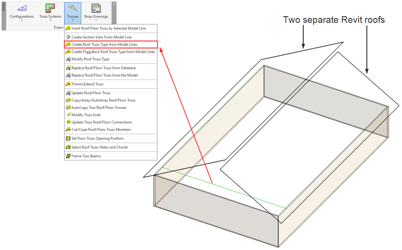
20. Create Uniquely Shaped, Parametric Truss Families, even for Multiple Roofs
The Truss Builder in Wood Framing Roof now lets you create uniquely shaped, parametric truss families based on model lines and even multiple roofs (in the past, we could create them only for one continuous roof modeled in Revit) for immediate use in your projects.
The built-in Truss Builder in Wood Framing Roof allows the user to draw a custom truss design and use it in a different project.
After drawing the Model Line at the correct level, we can select it and use “Create Roof Truss Type from Model Lines”:

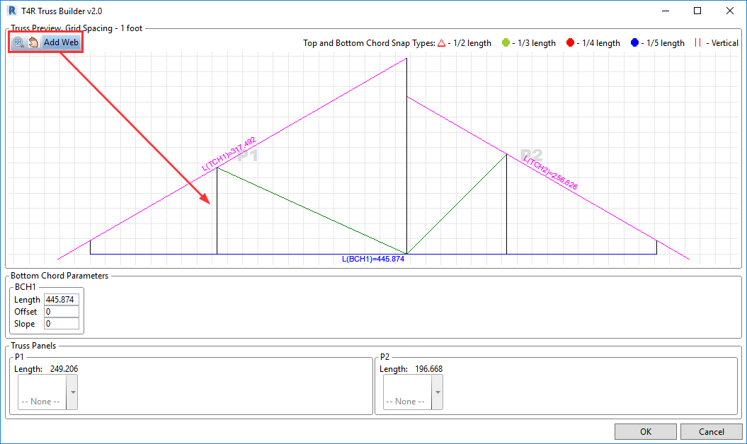
The Truss Builder window opens with a scheme created based on the Model Line (Bottom Chord) and the shape of Revit Roof (Top Chord), and we can sketch a custom web:

Result:

21. Modify Trusses using the Truss Builder
This update allowed you to use the Truss Builder to modify trusses, not just create new ones. Auto-generated trusses can be pushed to the Truss Builder, and from there, we can design the desired web.
Just select a Truss and use “Modify Roof Truss Type”:

The Truss Builder window will open, with a scheme already created based on the Top and Bottom Chords of the selected Truss. In that scheme we can go ahead and sketch a custom web:

Result:

22. Terminal Truss Roof
This update automatically converts a Step-Down Truss System to a Terminal System based on the span:

23. Replacing Trusses
This update made it really simple to replace a truss that’s already been generated in your roof.
In the Truss Systems drop-down menu, select one of the options: Select Trusses from the Same Group, Select Identical Trusses from the Same Group, or Select Trusses from the Same Grid. Then, replace them automatically by choosing the needed Truss from the Database or the Model (choose your option in the Trusses drop-down menu):

24. Overhang Framing
This software update brought you more truss overhang framing variations to choose from:

25. Create separate preassemblies for each joined opening
This feature lets you create separate preassemblies for joined opening, excluding other elements that extend across the openings (like top plate supports, etc.) from the preassemblies.
To use this feature, tick the box next to “Separate Joined Opening’s Preassemblies” in the Wall+ Default Framing Parameters window.

In the example below a preassembly will be created for the door and another for the window opening. The top support will be excluded from the preassemblies because it extends across both of them.

Then, by using Revit Filters, you can then automatically make shop tickets and schedules for each preassembly.

26. Add transportation braces (even across openings)
To add braces over openings, just tick “Allow Brace and Opening intersection” in the Framing Configuration.

27. Align Secondary Stud System with Project Base Point
This feature used to only be available for the main frame, but now it’s also possible to align the secondary stud system with the project base point. It lets you space and align all studs simultaneously. It works by means of the grid system to keep studs matched up throughout the whole project.

Just make sure to tick ON “Align with Project Base Point” in the Framing Configuration dialog.

28. More options for Brace Groups
More options that have been added to Brace Groups, allowing for a greater variety of bracing to be framed.

Brace groups don’t necessarily have to extend the whole height of the wall. They can be limited by horizontal elements:

29. Special layouts and splitting options for paneling
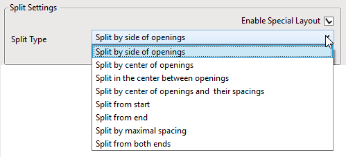
For paneling, it’s possible to use special layouts and apply additional splitting options.

Example: split by side of openings and enter minimal distances from Windows, Doors, Generic and System Openings, also, Minimum opening widths, like this:

And you get something like this:

30. Minimum dimensions for openings to be framed
Here is where you can enter minimum values for openings that should be framed.

Openings whose dimensions do not meet the threshold you enter will be ignored when framing:

31. Toggle “Configuration Visibility”
Configuration visibility can be controlled for unneeded confiugration types (secondary frame, nailers, sidings, etc.). And then they won’t appear in the “Framing Configuration” and “Link Wall” windows.

As evident from the updates described above, we’ve put a lot of work into our Wood Framing and Metal Framing BIM software over the past year to make sure it continues advancing to meet the needs of architects and structural engineers around the world.
Want to know more about our software for framing timber and steel walls, floors, trusses, rafters, and prefabricated roof panels in Revit? Click one of the banners below.


Want to find out how our framing solutions can streamline your Revit workflow?
Our professionals are here to help.

Contact us for a free, live demonstration given online by one of our BIM experts. Although you’re more than welcome to download a free trial, we encourage you to have a free demo first. That way you’ll be in a better position to evaluate the software during your free 14-day trial period because you’ll have answers to your preliminary questions and feel more comfortable with the basic workflow.
Related Client Stories:
- Scottish firm’s DfMA-level CLT Revit models benefit greatly from unique BIM software
- AGACAD becomes Autodesk AEC Industry Partner for Wood Framing
- AMV House thanks AGACAD for efficiency and customization gains in its prefab timber homes
- Today’s BIM-to-Fabrication Framing Solutions: An Interview with Renata Jociene
- Bela calls AGACAD metal framing and CNC solutions the “lifeblood” of its building design business


