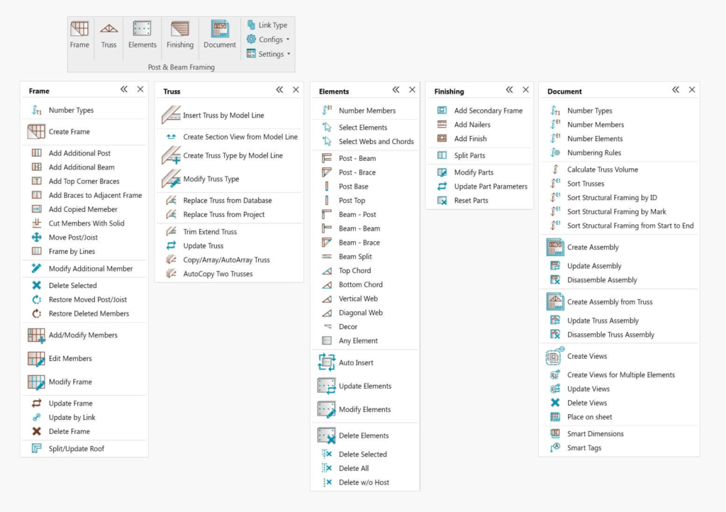
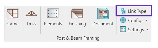
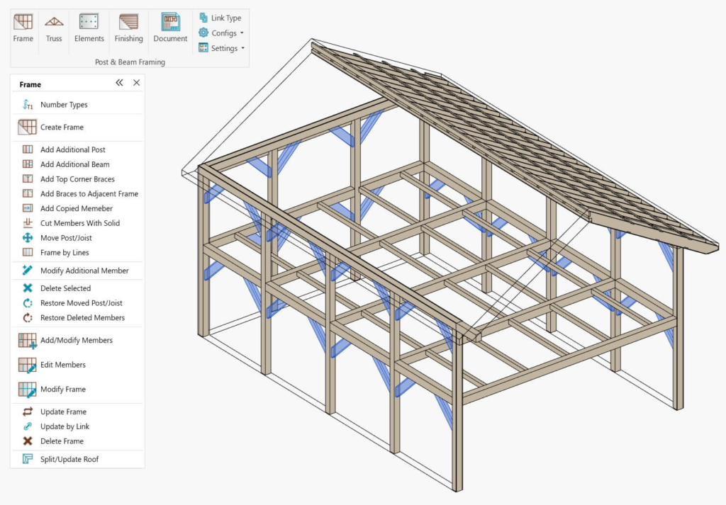
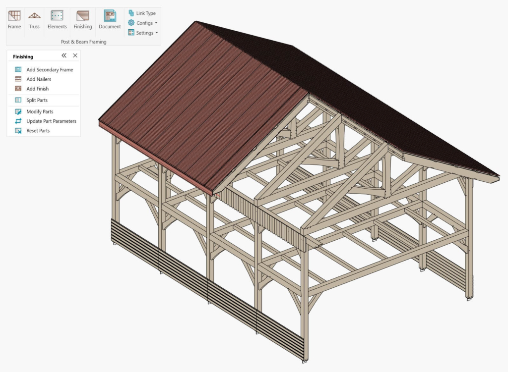
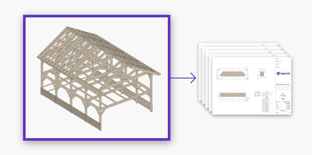
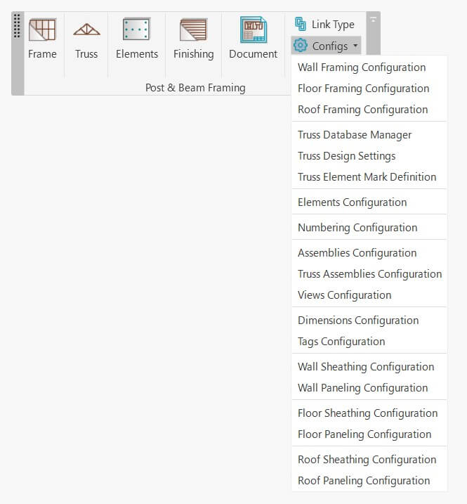
We recently released a major UI enhancement of our Be.Smart Post & Beam Framing add-on for Autodesk® Revit® so that the extension would be easier to use and the workflow more intuitive. Here’s what the top-level menu looks like, with the menus unfurled below:
In this post, I will go through the basic workflow so that you can implement Post & Beam Framing on your own project. Need an in-depth tour of the UI? See our post.
Please note, that these instructions are meant to make the experience of testing the software as smooth as possible, so I’m going to explain how to do that using our sample configurations and families. Have in mind that all these sample rules can be modified to your needs and standards. That goes for all configurations for Framing, Connections, Numbering, Shop Drawings, etc.
So, here’s how to start framing from scratch with heavy timber in Revit using our Be.Smart Post & Beam Framing add-in.
SETUP
After starting a new Revit project, make sure you save it.

STEP 1: Load families
Choose the sample families to be loaded into the current project. The software comes with sample metric and imperial families for creating frames with connections common for heavy timber structures, tag families, and sample schedules.
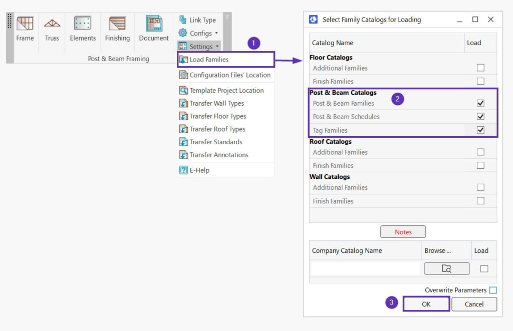
If you’ll be designing only the heavy timber structure, then it is sufficient to only load families and schedules from the Post & Beam Catalogs (2 in the above image). In the Post & Beam Catalogs, select the available samples:
- Post & Beam Families – sample framing and connection families for creating frames with common connections used in heavy timber structures
- Post & Beam Schedules – sample schedules
- Tag Families – sample tag families
It’s optional to select: Floor Catalogs / Roof Catalogs / Wall Catalogs. Under each of those catalogs, you have Additional Families and Finish Families.
- Additional Families – sample families for creating additional floor/roof/wall layers, like timber secondary frames, horizontal or vertical nailers, battens, etc., or main timber frames (supporting structure) with studs/joists
- Finish Families – sample families for creating floor/roof/wall finish layers, like flooring, roofing, or siding
After loading, you can find the families by going to Project Browser → Families under Structural Framing, Structural Connections, Annotation Symbols and Generic Models categories.
STEP 2: Transfer standards (optional)
The Template Project is a Revit file with sample Wall, Floor and Roof types, standards, and annotations. The Template Project feature allows you to transfer all needed information from a template project – so that you don’t have to create Wall/Floor/Roof types and other needed elements or standards in every new project from scratch.
Before working with the software, we recommend using the Transfer features (2-6 in the image below).
Template Project Location – the path to your template project. Here, you can map your own Revit project that has all needed Wall, Floor and Roof Types, as well as annotations. Note that our Post & Beam Framing add-in comes with a sample Template Project, which is mapped here automatically.
When starting out or just testing the software, you can use the sample Post & Beam Framing project that is available in the e-help pages and map it here. Later on, of course, you can create/use your own:
- Transfer Wall Types – transfer wall types from the projects defined in ‘Template Project Location’ to the current project.
- Transfer Floor Types – transfer floor types from the projects defined in ‘Template Project Location’ to the current project.
- Transfer Roof Types – transfer roof types from the projects defined in ‘Template Project Location’ to the current project.
- Transfer Standards – Opens Revit’s ‘Transfer Project Standards’ dialog window. You then need to manually select various styles, types and settings which need to be transferred from the Template Project File to the current project.
At least these 6 options must be selected:
Text Types
View Reference Types
View Templates
Viewport Types
Dimension Styles
Filters
You can select more options if needed.
5. Transfer Annotations – loads and overwrites Tags, Callout Heads, Section Heads, Section View Types, Title Blocks and copies Legend Views, Schedules from the projects defined in the ‘Template Project Location’ to the current project.
MODELING
After you have loaded the needed sample families (Step 1 – mandatory) and transferred all types and standards to your new/current project (Step 2 – optional), then you can proceed to create the architectural model that will later be framed automatically.
STEP 3: Creating basic Revit walls, floors and roofs
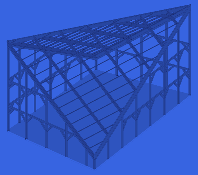
In this example, I modeled a few walls, a floor, and a roof using types transferred from the sample Post & Beam framing project:
Once the model has been created, you can start using the sample configurations to create the Frames.
STEP 4: Link Type
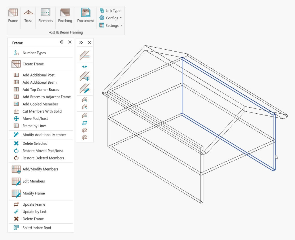
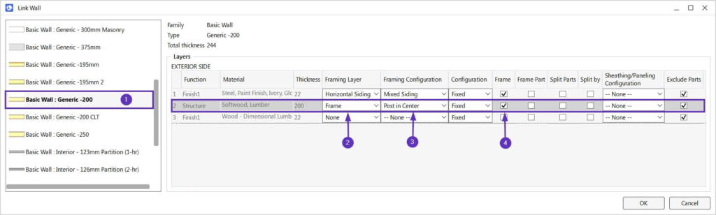
The walls/floors/roofs can have the needed number of layers in order to create your structure with optional additional layers, like battens, sidings, etc. In this example, we’ll focus on the most important settings for the main Frame layer.
Note: this example is with a Wall, but the logic is the same for Floors and Roofs.
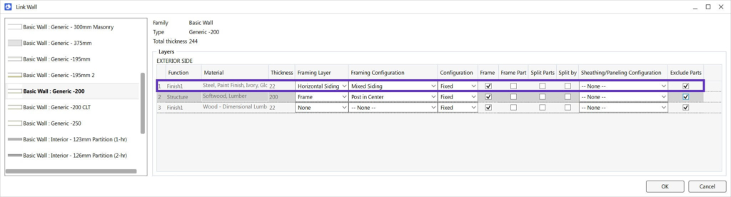
In the image above, the numbers indicate the following:
- Selected wall/floor/roof type
- ‘Frame’ should be selected in the ‘Framing Layer’
- ‘Framing Configuration’ – select a framing configuration with the definition of all framing parameters. A sample configuration that comes with the Post & Beam Framing software was used here, but you can also create your own later on.
- ‘Frame’ – choose whether layers should be framed during the framing process.
STEP 5: Create Frame
I demonstrate the whole process starting from STEP 5 in this video:
To create the frame, first run the Number Types command. This will number all host elements: walls, floors, and roofs, by your own custom rules:
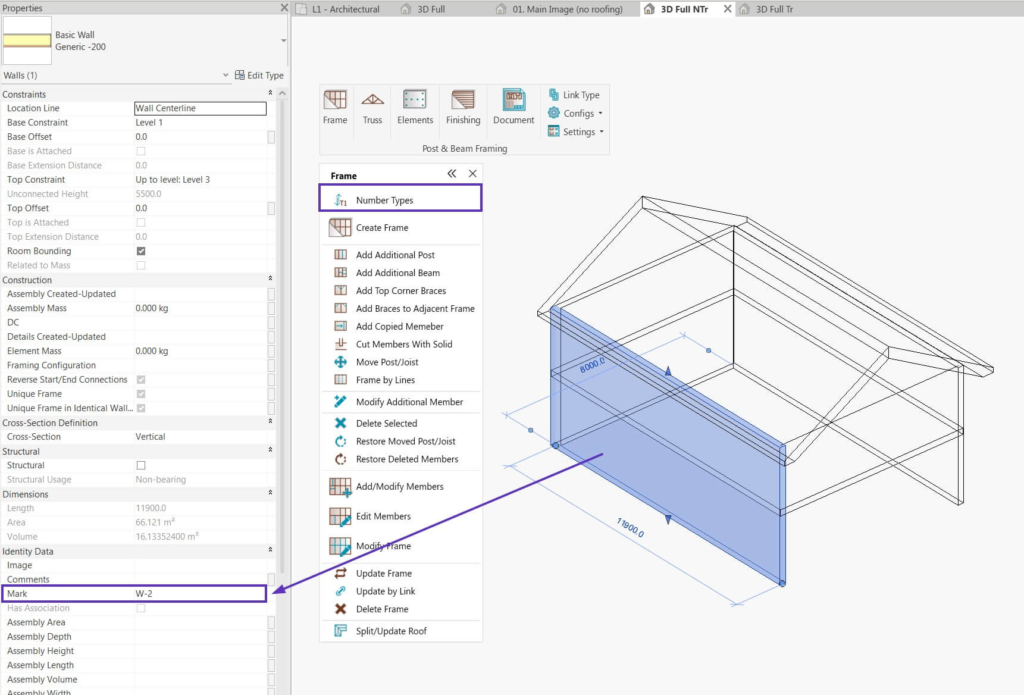
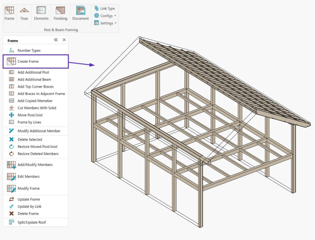
Now, select all the walls, floors and roofs you want to frame and click Create Frame.
In this example, wall, floor and roof frames were generated according to the chosen sample configurations:
Please note, that these sample configurations can be modified to each user’s needs and standards. That goes for all configurations for Framing, Connections, Numbering, Shop Drawings, etc.
STEP 6: Modify/Update (as needed)
The add-in is very flexible when it comes to modifying frames after they’ve been generated via the settings in your configurations. You can modify the frames using features from the ‘Frame’ window if you need to. The following are just a few examples among many possible ways and workflows.
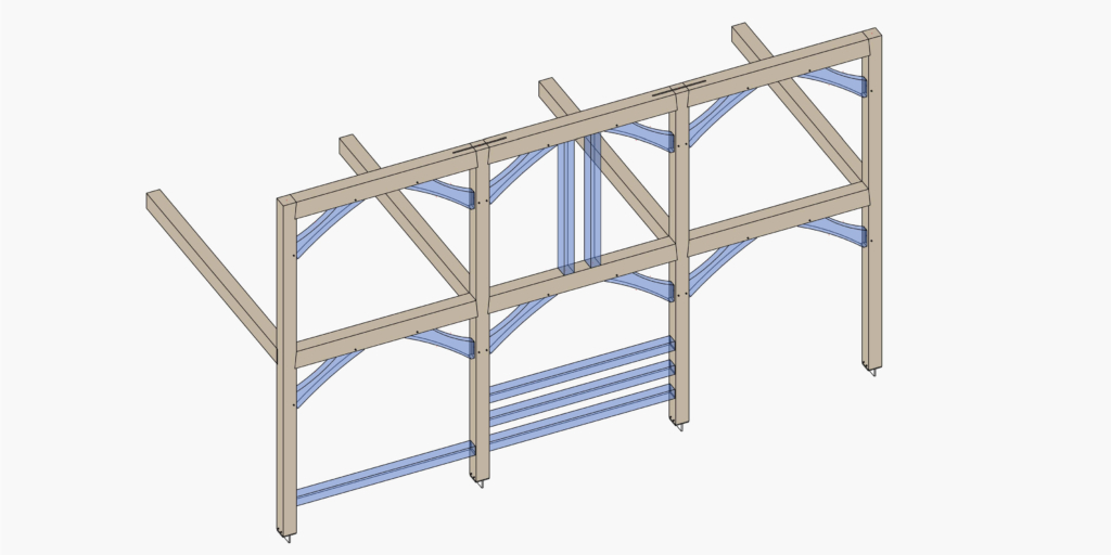
In this example, additional elements were added automatically:
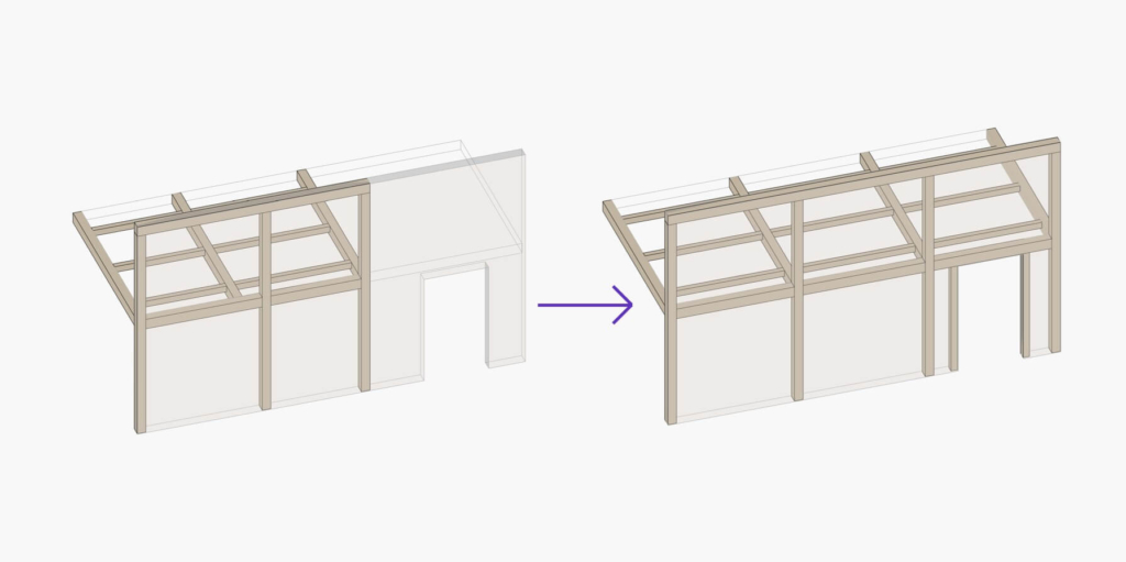
In this example, the frame was updated based on the changes made in the architectural model: the wall and floor were enlarged, and an opening was added:
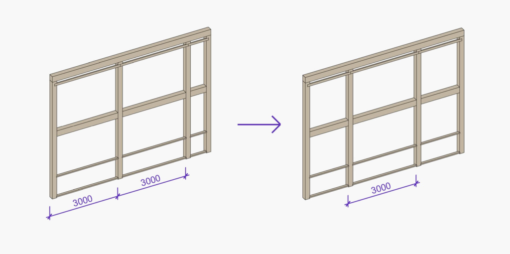
In this example, the instance of the framing configuration was modified to change the post layout. Instead of distributing posts from the start of the wall, their spacing is now centered on the wall’s midpoint:
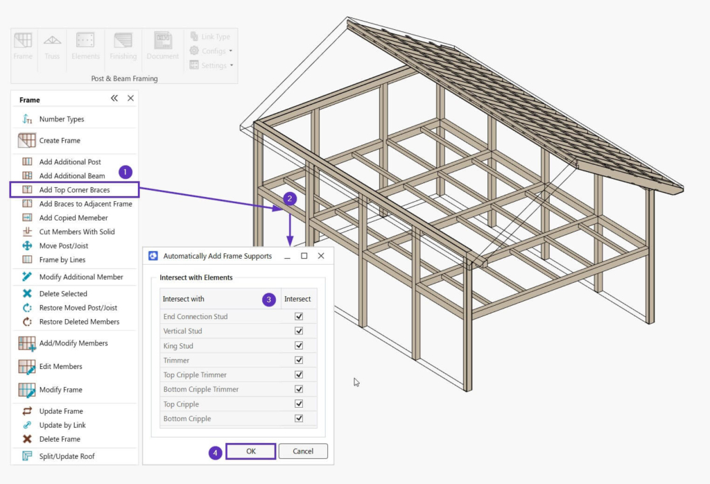
STEP 7: Add braces
Once you have frames, you can add braces. Click Add Top Corner Braces (1), and select one of the horizontal elements that should be supported (2). Then, you can choose vertical framing members that should intersect with the supported horizontal elements (3), and click OK (4).
Then, you can continue selecting all horizontal elements that should be supported and braces will be added automatically:
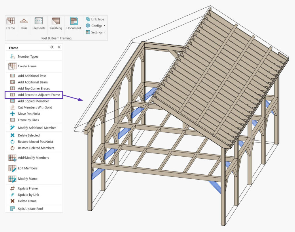
And if you wish to add braces between framing elements that do not belong to the same frame (for example, connected walls or wall posts and floor joists, etc.), then use the Add Braces to Adjacent Frames command, and select elements one by one between which the brace should be added:
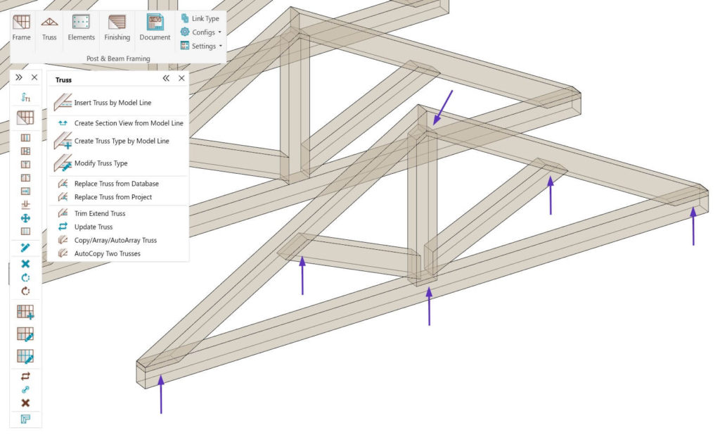
STEP 8: Insert trusses
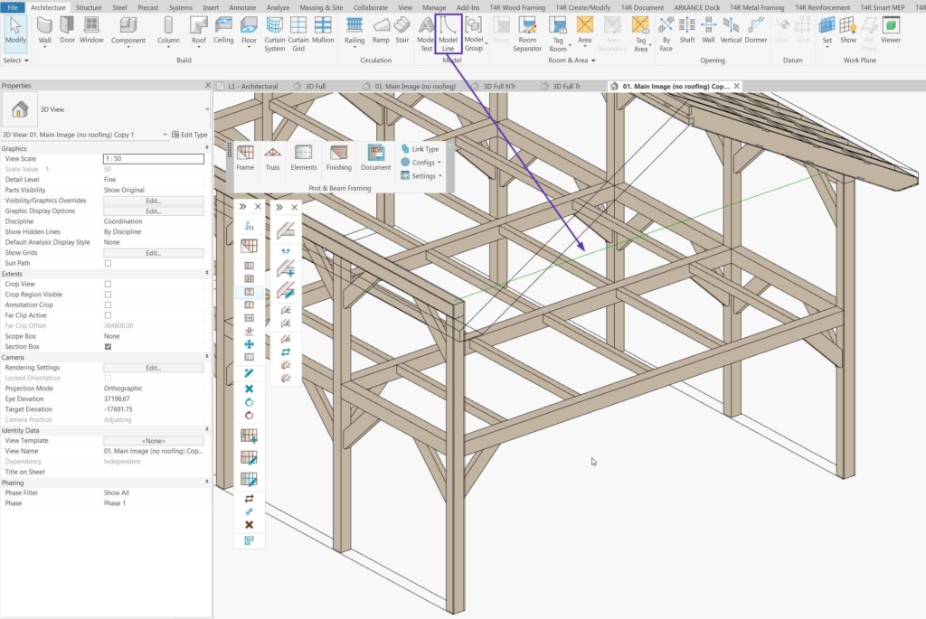
You can insert a truss by model line and then copy/array it across the whole roof. Before inserting the truss, you need to draw a model line that will act as a bottom chord boundary line. Here’s how to do that.
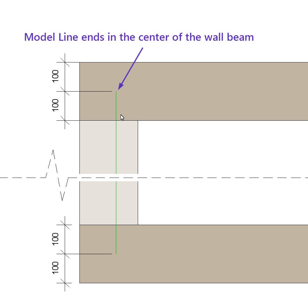
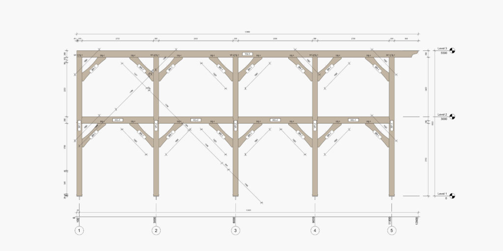
Pay attention to the ends of the model line – that’s where the location line of the vertical web on the edge of the truss will be. In this example, the Truss vertical web will be the same size as the wall beams, so I drew the model line from the center of one wall beam, to the center of the other wall beam, as you can see in this plan view:
Then, select the Model Line (1), use Insert Truss by Model Line (2), select a sample truss family (3), and click OK (4):
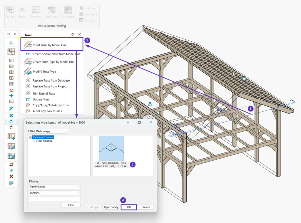
Please note, that the sample Truss family can be modified to each user’s needs and standards, and you can create new Truss families.
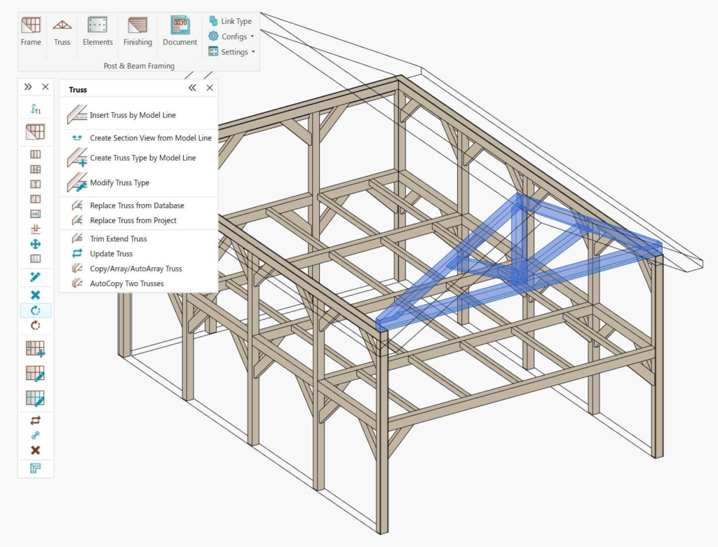
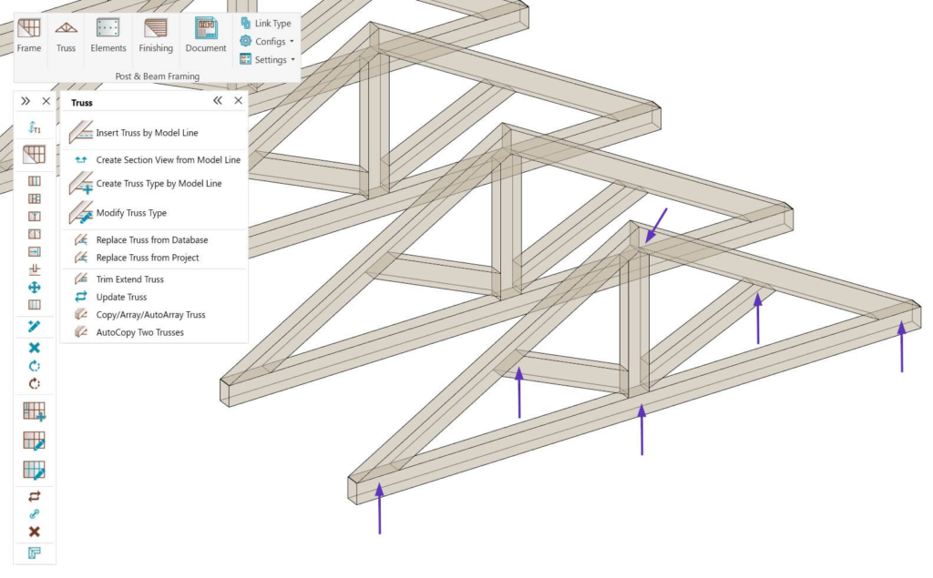
As a result, a truss is inserted automatically. The model line acted as a boundary line for the bottom chord, the roof for the top chords, and the slopes were read from the modeled roof:
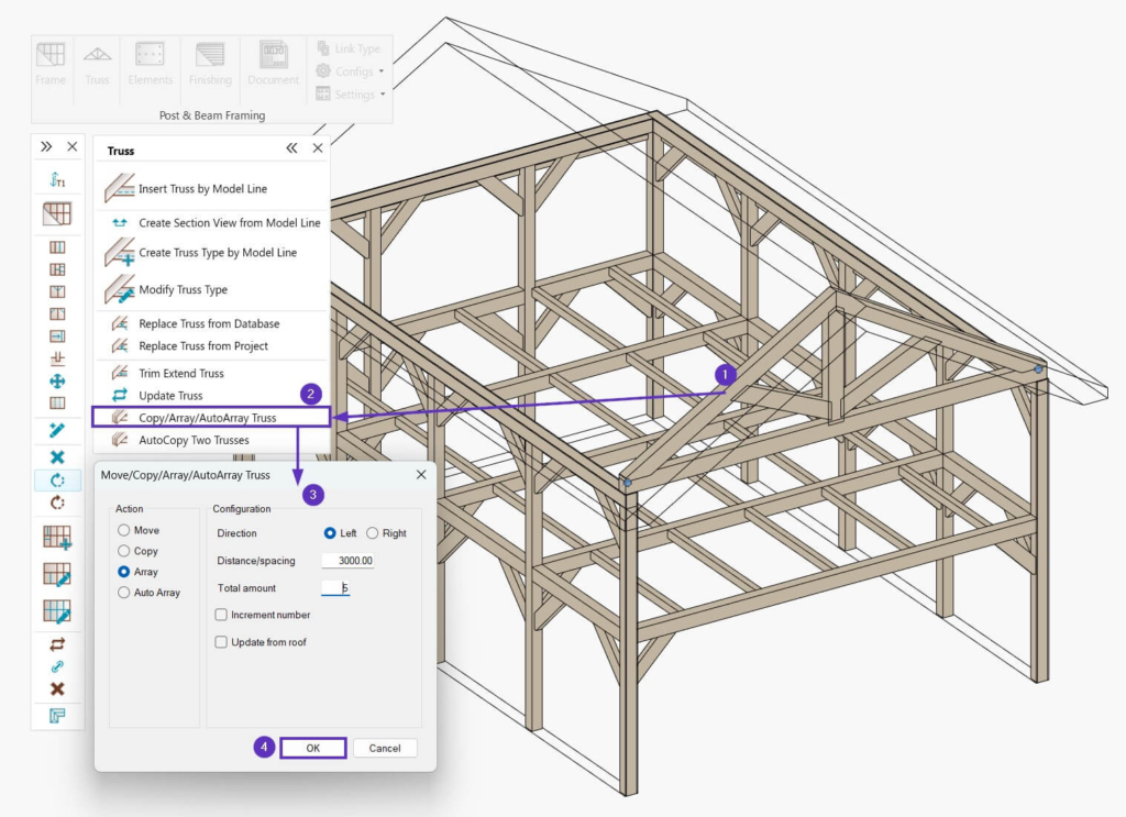
Now, select the inserted Truss (1), use Copy/Array/AutoArray Truss (2), choose the method of distribution as well as values for the spacing and the total number of trusses for your roof (3), and click OK (4):
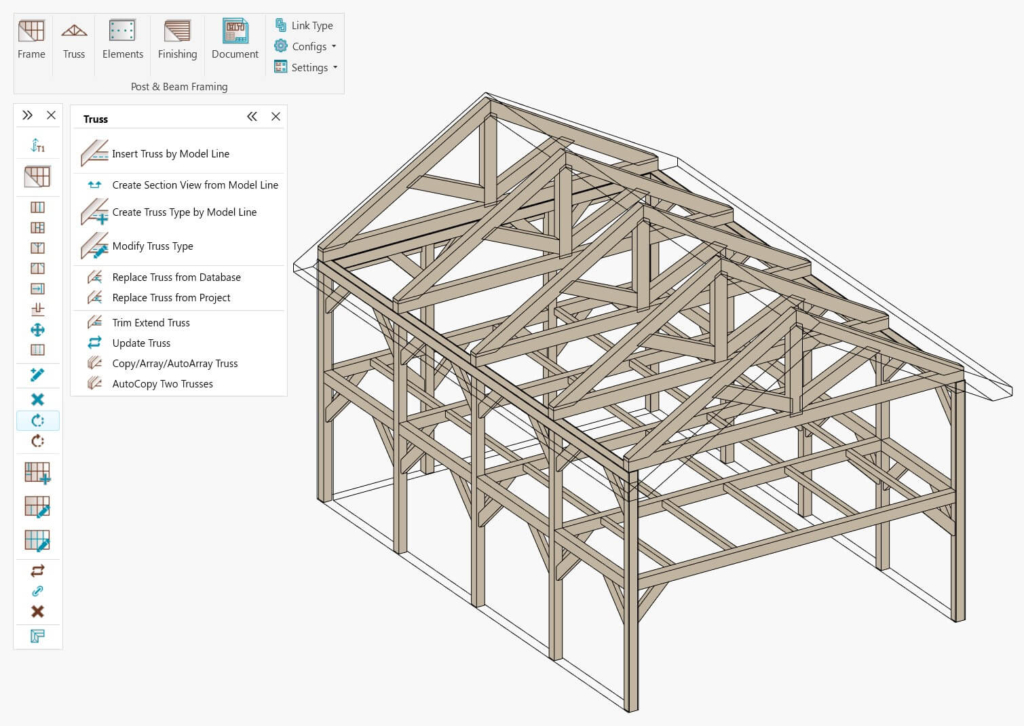
As a result, trusses are arrayed automatically:
Now, it’s time to address the overlaps between the top, bottom chords and webs:
To do that, auto-select the elements that should cut intersecting elements, and create the proper cuts. Use Select Webs and Chords (1), select Vertical Webs (2), click OK (3), and use Cut Members with Solid (4):
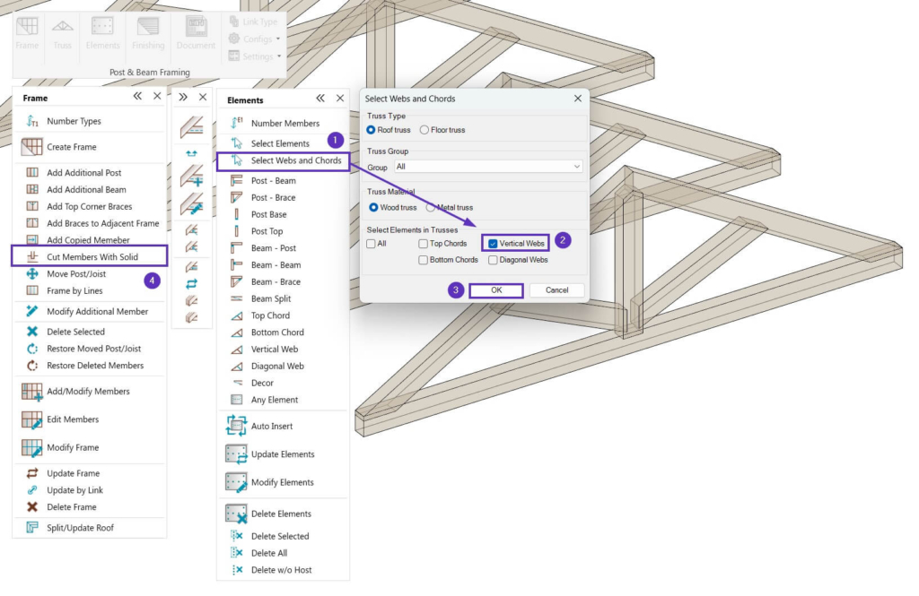
Now that you’ve done it for Vertical Webs, do that same process but for for Top Chords and then again for Bottom Chords. I.e., in step 2 of 4 above, select Top Chords and then the third time around select Bottom Chords.
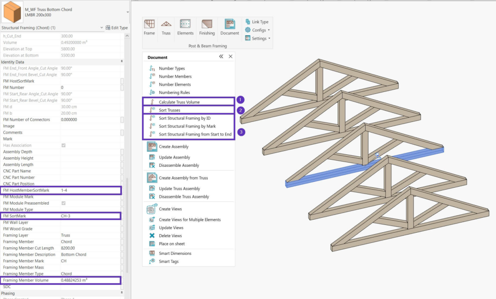
As a result, all elements in trusses have proper cuts:
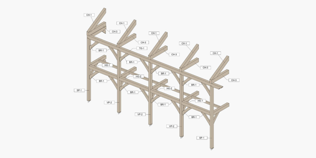
Now that trusses have been created and cleaned up, you can calculate Truss Volume (1), Sort Trusses (2) and number truss members by a chosen rule. Completing this step will ensure that Structural Connection elements (which will be distributed later) have their host parameter values transferred:
STEP 9: Insert common heavy timber structural connections
Once you have all walls, floors and roofs framed, you’re ready to create connections common for heavy timber structures. Commands in the Elements window let you insert hundreds of elements into your project with just a few clicks – saving you hours and ensuring accurate modeling of highly detailed projects. You can easily follow project changes and quickly modify and update joints as needed (like mortise and tenon joints, lap joints, dovetails, etc.).
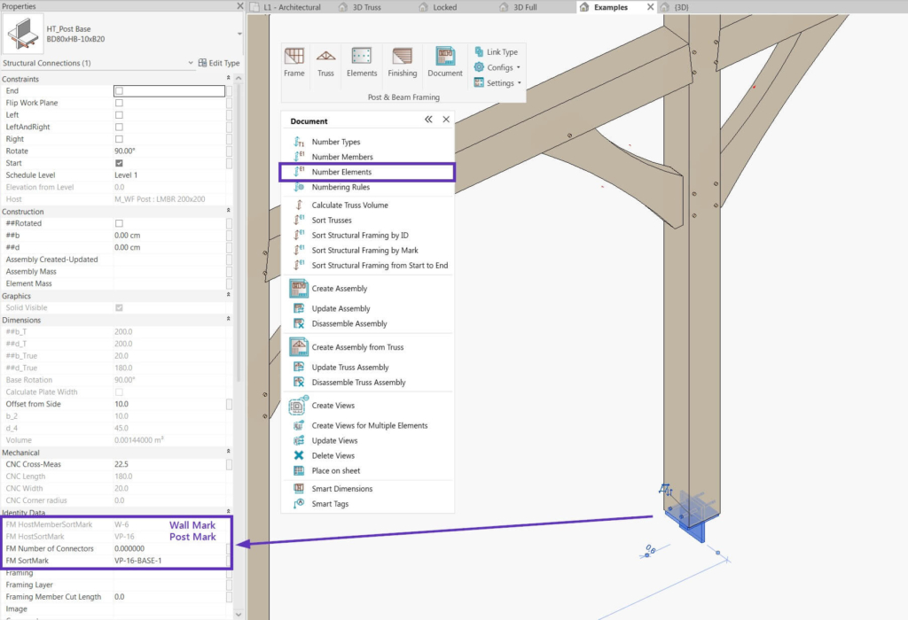
Before inserting connections, use the Number Members command to automatically number all Structural Framing elements in your project according to your own custom rules. And any Structural Connections inserted later will inherit the parameter values of their hosts (i.e. numbered Structural Framing elements):
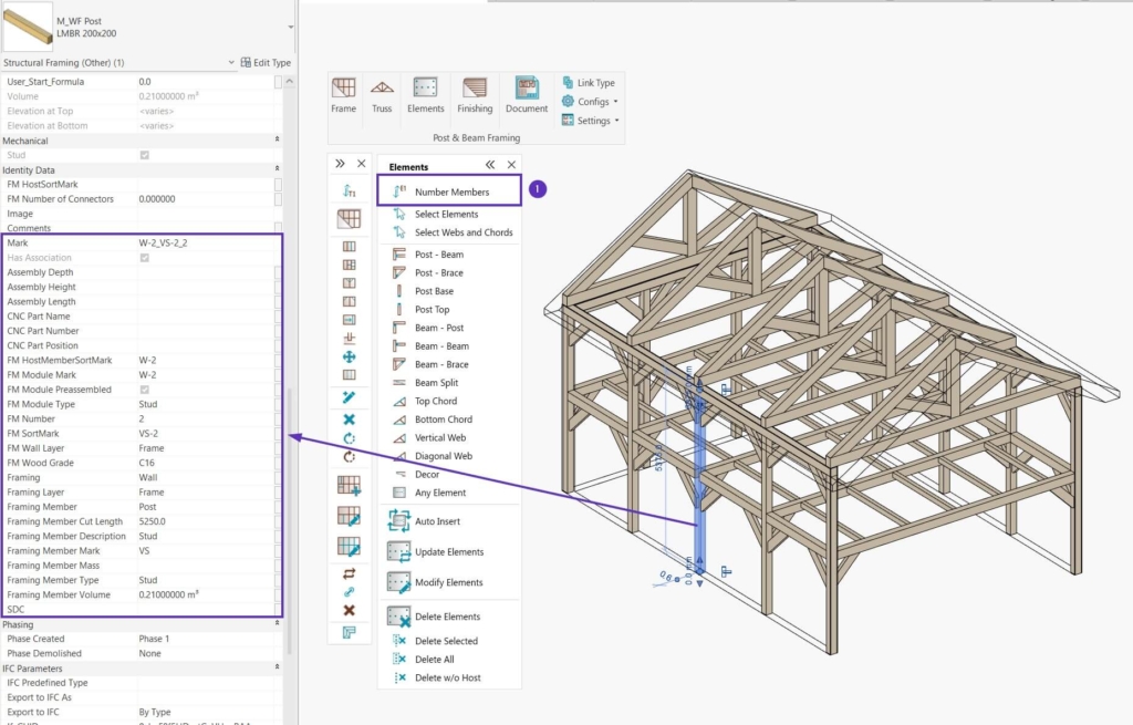
As you can see in the image above, the selected post’s parameter values (like ‘Mark’ and ‘FM Sort Mark’) were filled in automatically, as for all Structural framing elements in your project. Also, Structural Framing elements inherited their host’s (Wall’s) ‘Mark’ parameter value, which was filled in the ‘FM HostMemberSortMark’ because we used the ‘Number Types’ command earlier.
Now, select the needed Structural Framing elements and insert Structural Connection elements between certain element connections (e.g., between a post and a beam) or positions (e.g., on a post’s base) predefined in your Elements Configurations.
Please note, that all these sample rules can be modified to each user’s needs and standards and you can also use your own Structural Connection families.
First off, auto-select needed elements using the Select Elements and Select Webs and Chords commands (1) (you may also select them manually) and then use a command for inserting Structural Connection elements (2):
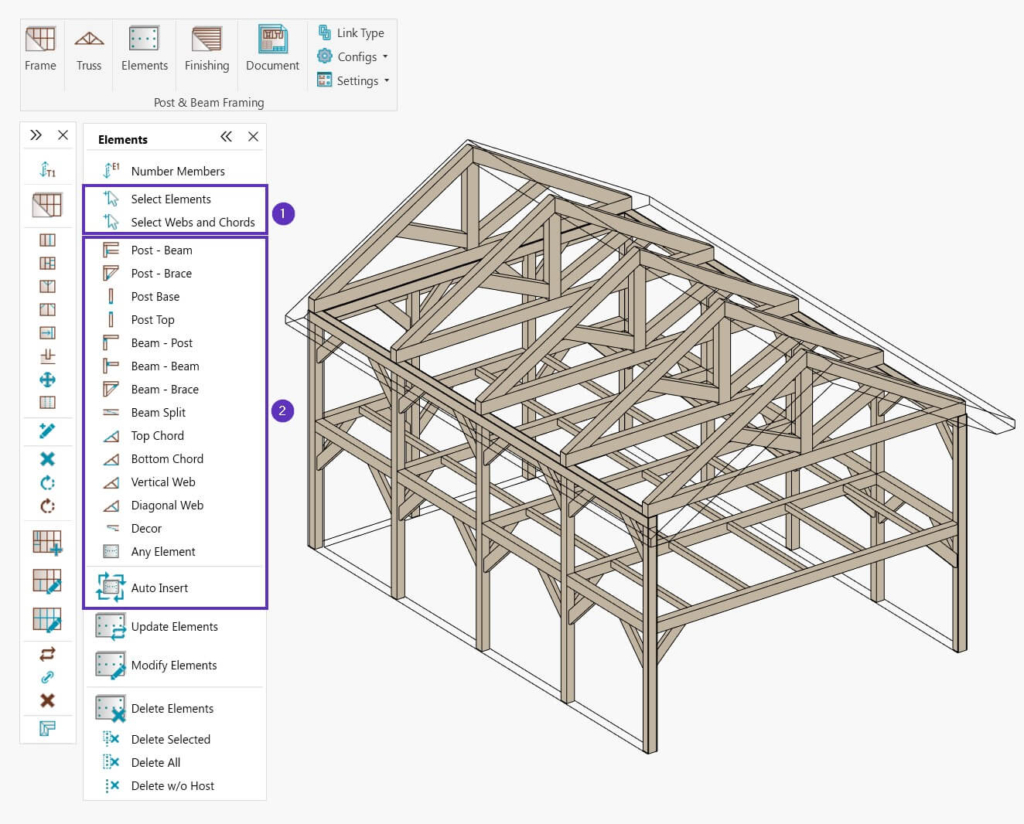
As you can see in the image above, some of the commands for inserting Structural Connection elements are grouped based on the element intersections or positions, as well as other elements, like decorations.
The following commands will open a window with a specific configuration group:
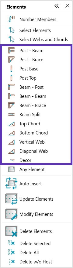
Here’s what each is for:
Visual example
Command
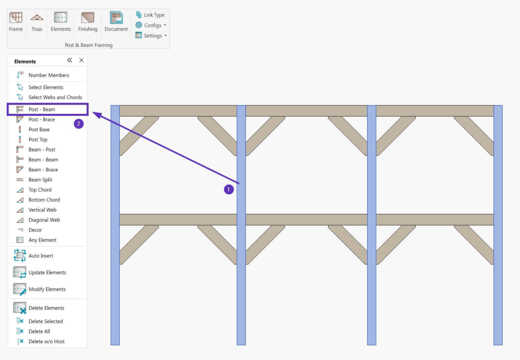
Post – Beam
To insert elements on post and beam intersections, select the posts and then choose the Post – Beam command.
Post – Brace
To insert elements on post and brace intersections, select the posts and then choose the Post–Brace command.
Post Base
To insert elements on the base of the posts, select the posts and then choose the Post Base command.
Post Top
To insert elements on the top of the posts, select the posts and then choose the Post Top command.
Beam – Post
To insert elements on beam and post intersections, select the beams and then choose the Beam – Post command.
Beam – Beam
To insert elements on beam and beam intersections (for example, floor beams), select the beams and then choose the Beam – Beam command.
Beam – Brace
To insert elements on beam and brace intersections, select the beams and then choose the Beam – Brace command.
Beam Split
To insert elements on split beams, select the split beams and then choose the Beam Split command.
Top Chord
To insert elements on the truss top chords and intersecting elements (for example, webs), select top chords and choose the Top Chord command.
Bottom Chord
To insert elements on the truss bottom chords and intersecting elements (for example, top chords and webs), select bottom chords and choose the Bottom Chord command.
Vertical Web
To insert elements on the truss vertical webs and intersecting elements or decor (for example, diagonal webs or arch cuts), select vertical webs and choose the Vertical Web command.
Diagonal Web
To insert elements on the truss diagonal webs and intersecting elements or decor (for example, webs or arch cuts), select diagonal webs and choose the Diagonal Web command.
Décor
To insert various decoration elements, for example, arch cuts for braces or end cuts for beams, select needed elements and choose the Decor command.
You can also insert Elements by using the Any Element or Auto Insert commands.
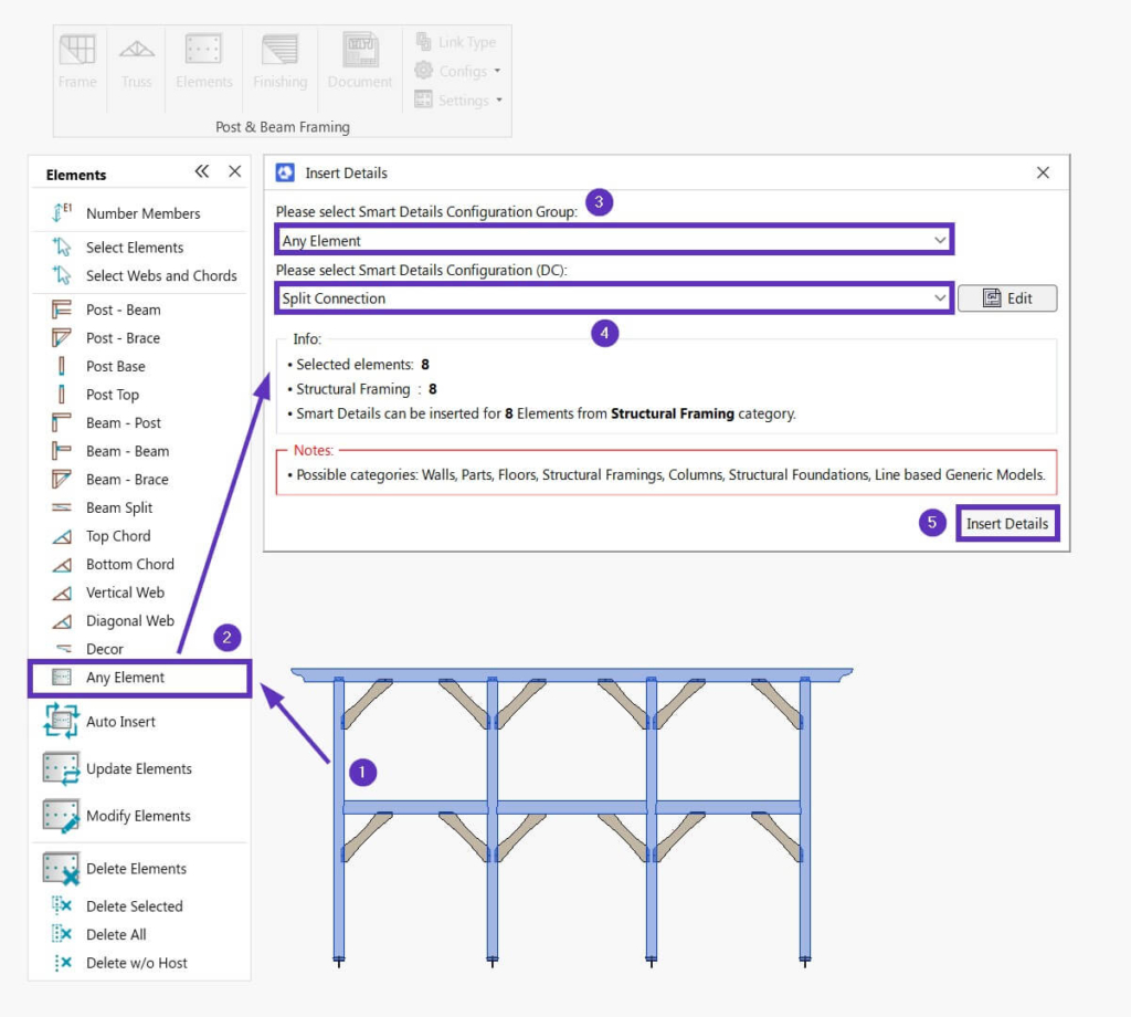
Any Element
To insert elements from any group and any configuration from a selected group:
- Select one category of Host elements (Walls, Structural Framing, Parts, etc.)
- Click Any Element
- Select Elements Configuration Group
- Select Elements Configuration
- Run Insert Details
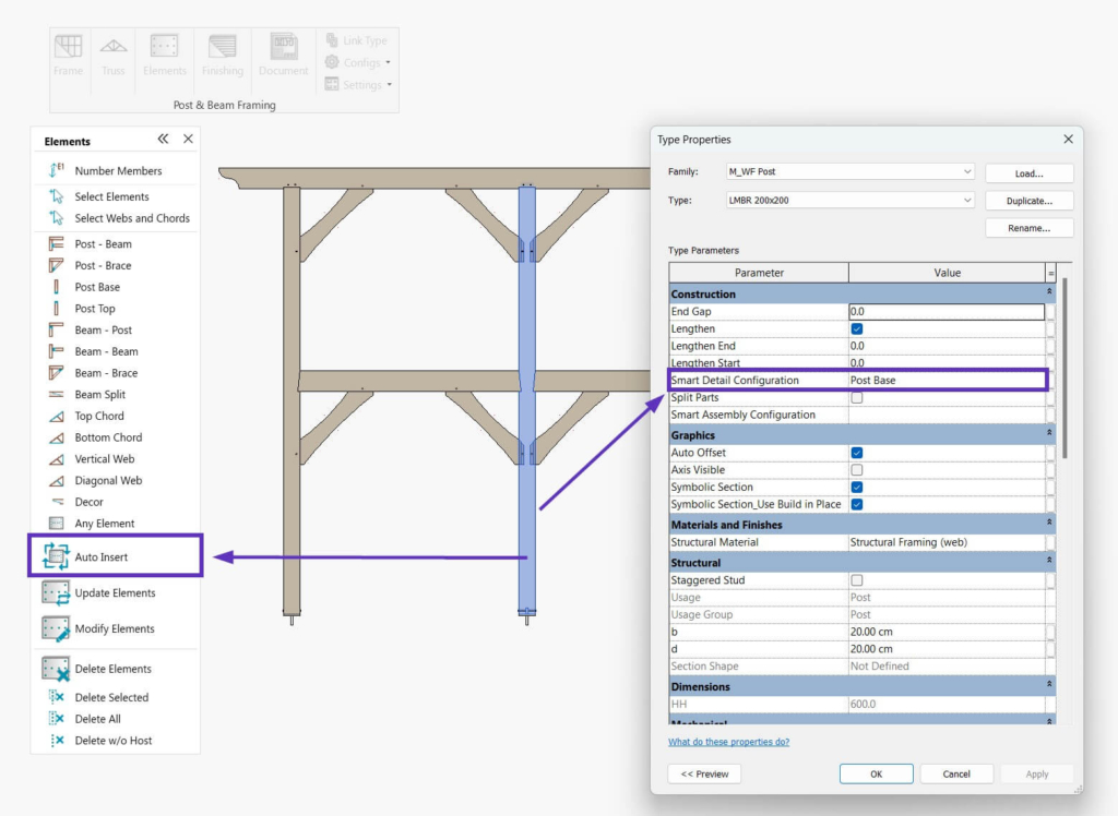
Auto Insert
When you start using Post & Beam Framing, the tool adds a Smart Details Configuration shared parameter to the project. This parameter is added as a Type parameter for all Categories compatible with Smart Connections: Walls, Floors, Roofs, Parts, Columns, Structural Framing, Pipes, etc.
To use Auto Insert, you have to fill that parameter with the name of the Configuration that you want to use. After executing the Auto Insert command, the tool will not ask you to pick a configuration; instead, it will read the name of the Configuration from the ‘Smart Details Configuration’ parameter and start inserting elements.
As an example, let’s insert Elements between posts and intersecting beams.
First, select the posts, and use the Post – Beam command:
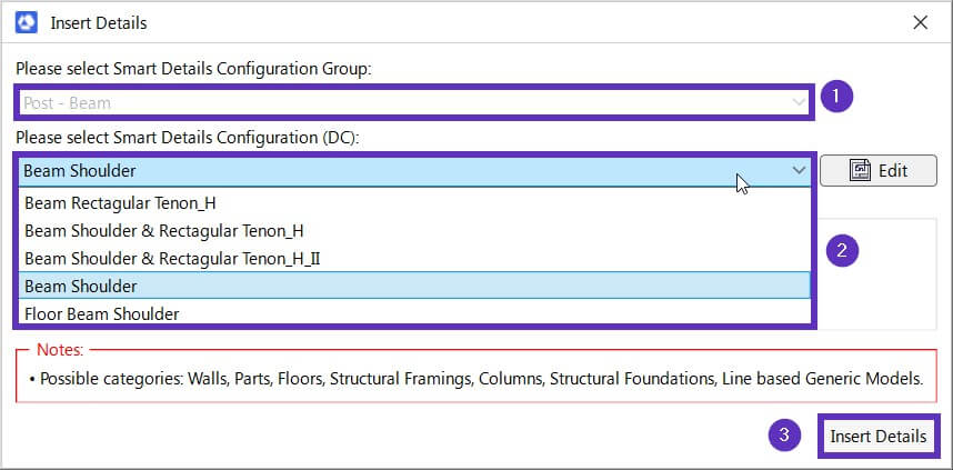
The Insert Details window will open for the ‘Post – Beam’ configuration group (1). Select a configuration (2) from that group, and click ‘Insert Details’ (3):
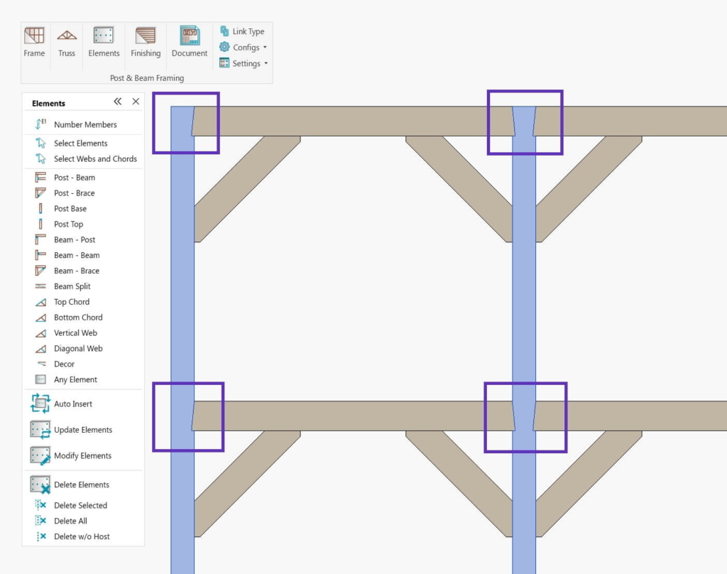
Structural Connection elements will be distributed automatically on post and beam intersections, based on the selected configuration:
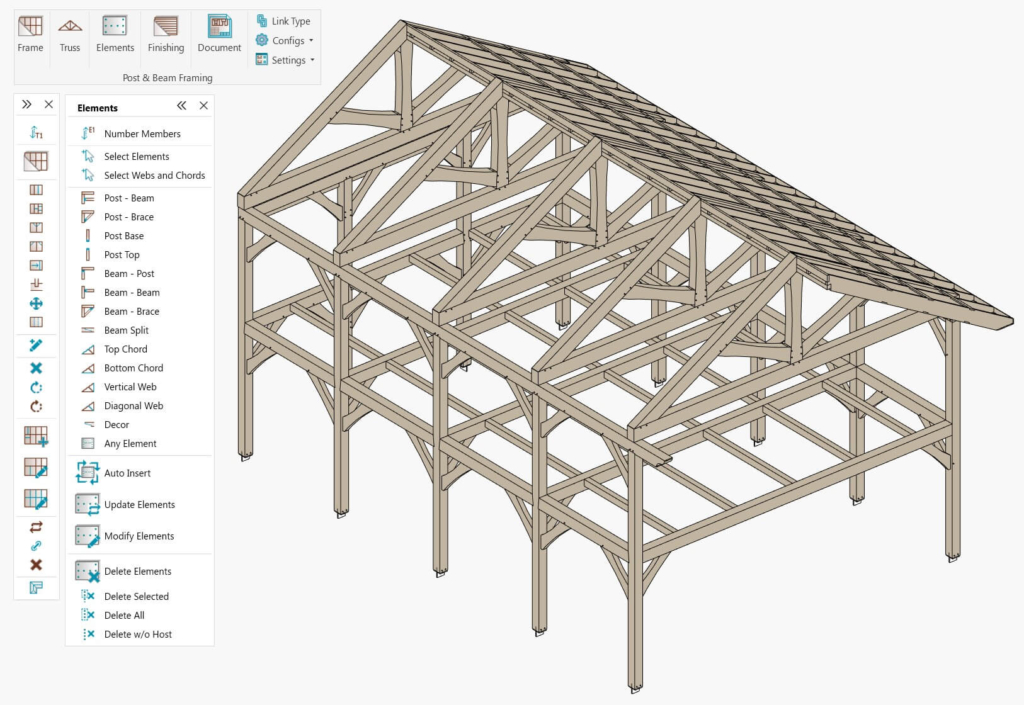
And this is the result with all needed Structural Connection Elements distributed:
Now, let’s take a closer look at some examples — all of which can be done using the sample configurations that come with Post & Beam Framing.
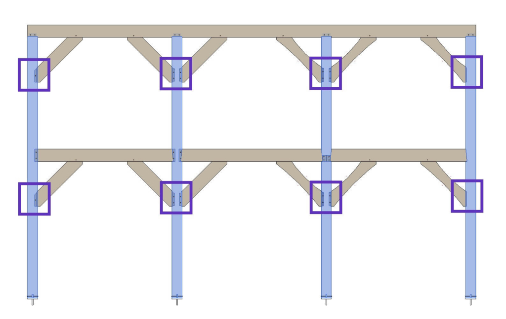
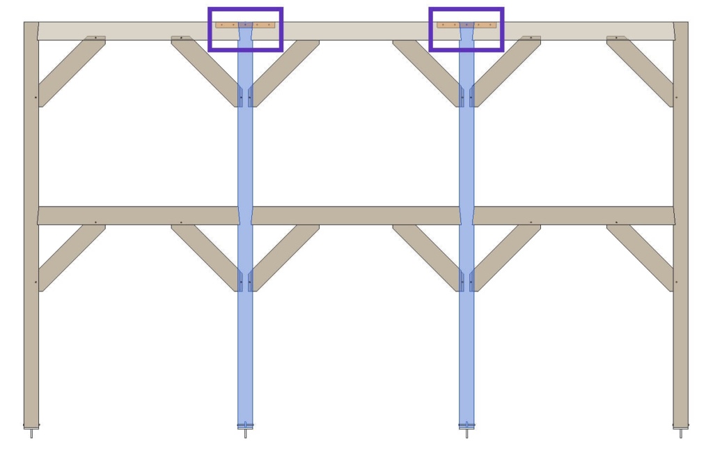
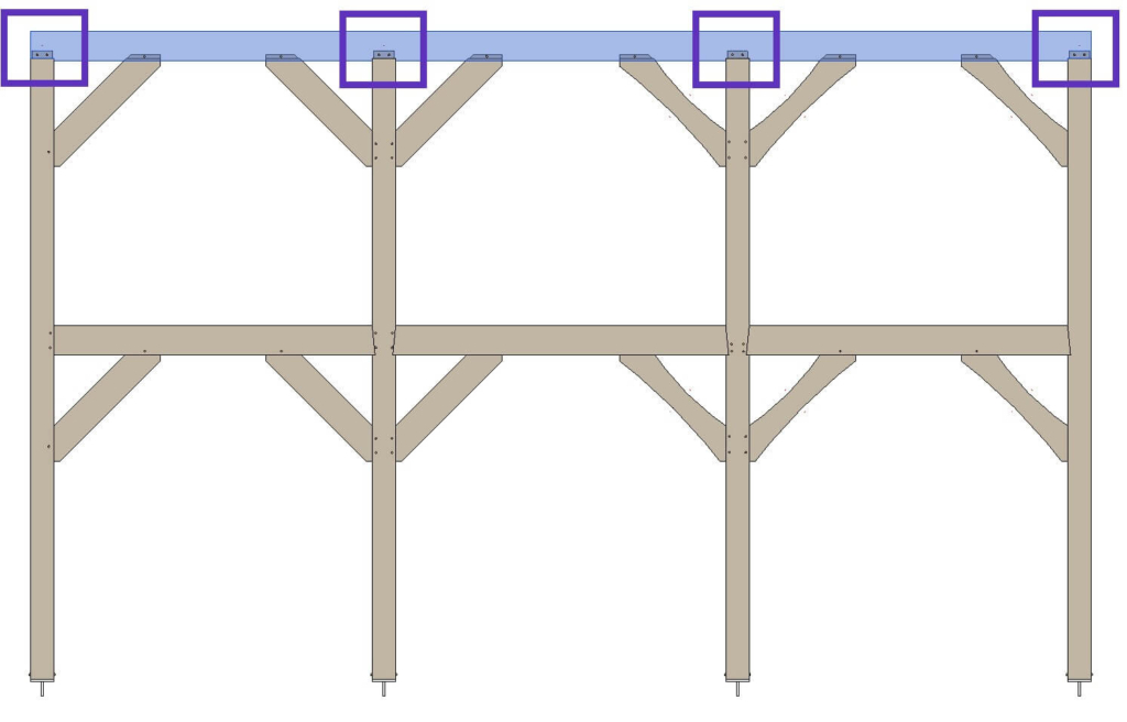
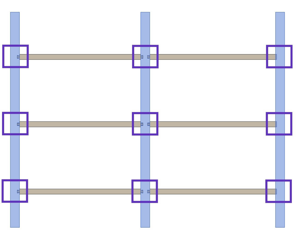
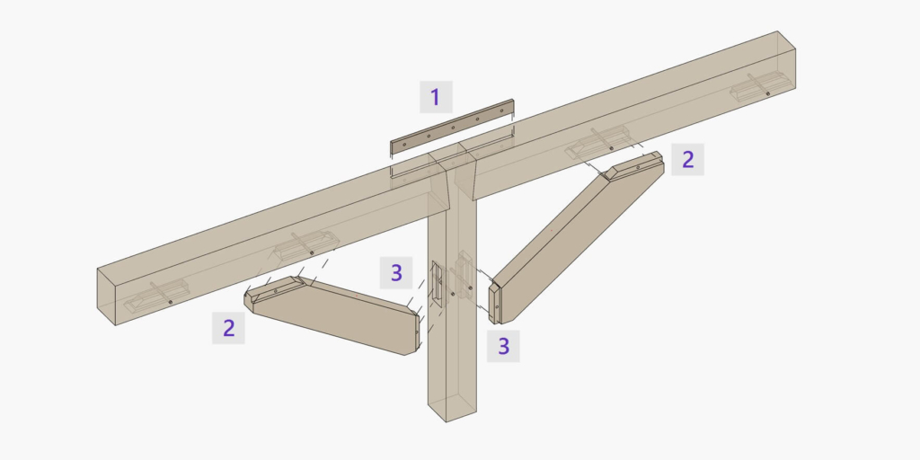
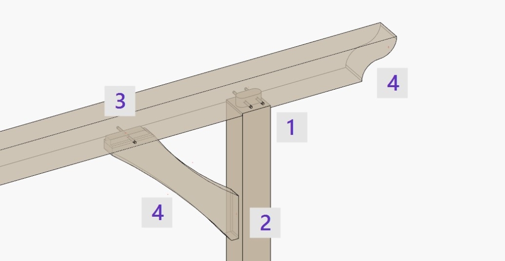
Elements inserted with the Post Top (1), Beam – Brace (2) and Post – Brace (3) commands:
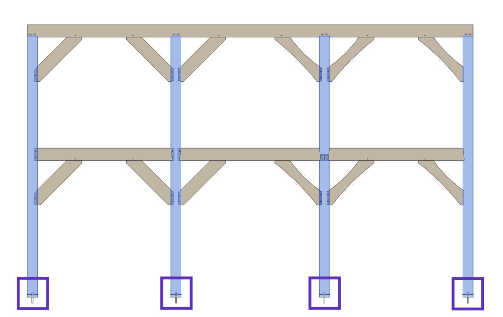
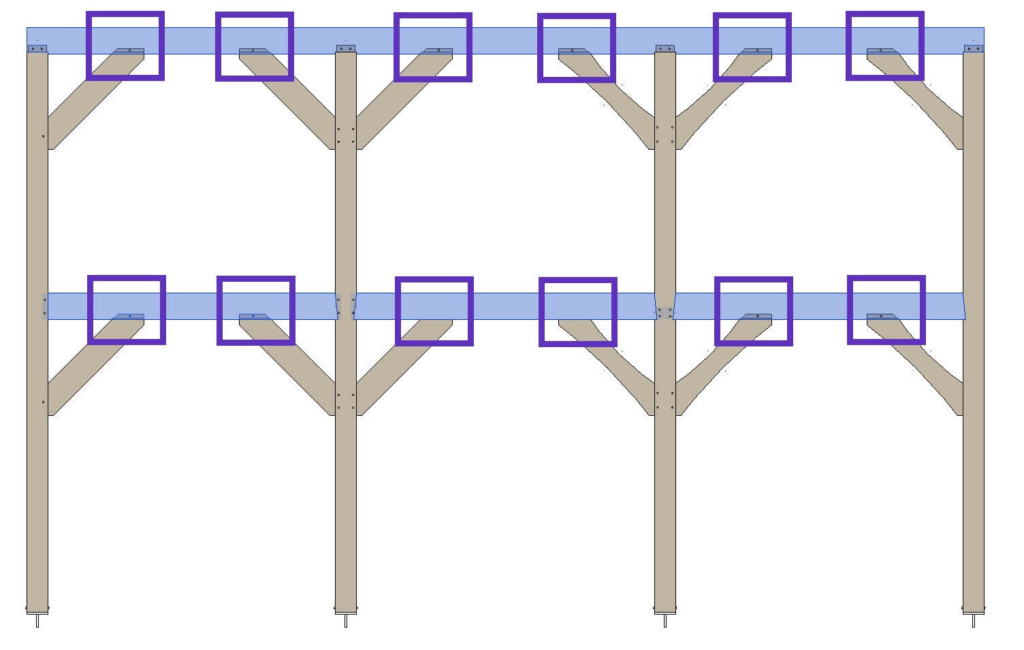
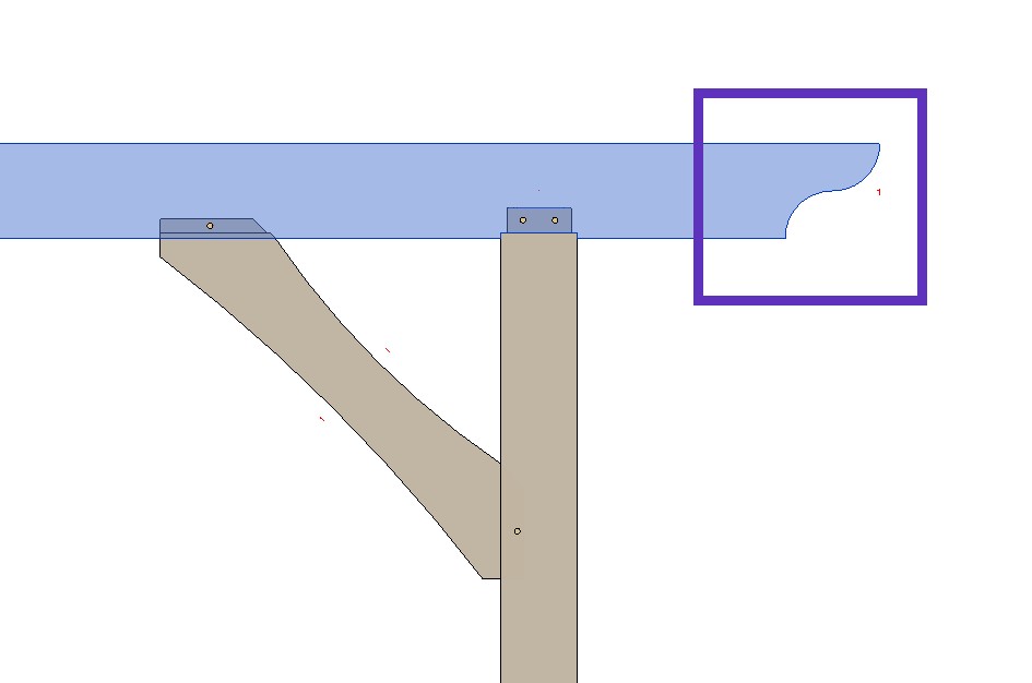
Elements inserted with the Beam – Post (1), Post – Brace (2), Beam – Brace (3) and Decor (4) (yields end cut for the beam and arch cut for the brace) commands:
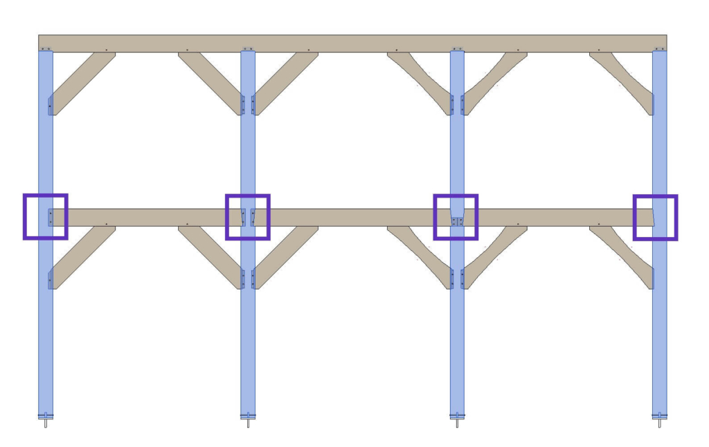
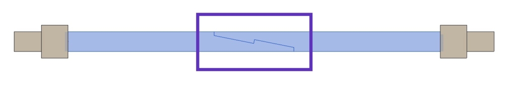
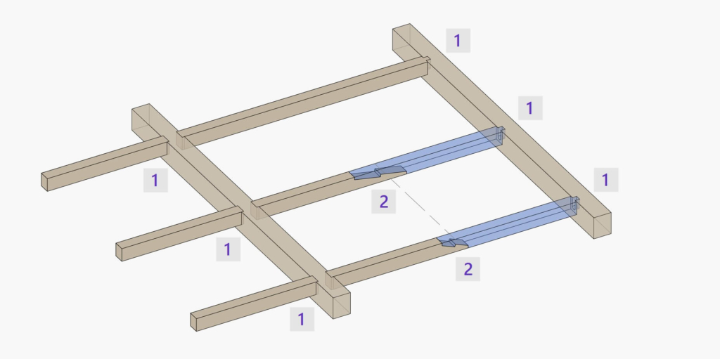
Elements inserted with the Beam – Beam (1) and Beam Split (2) commands:
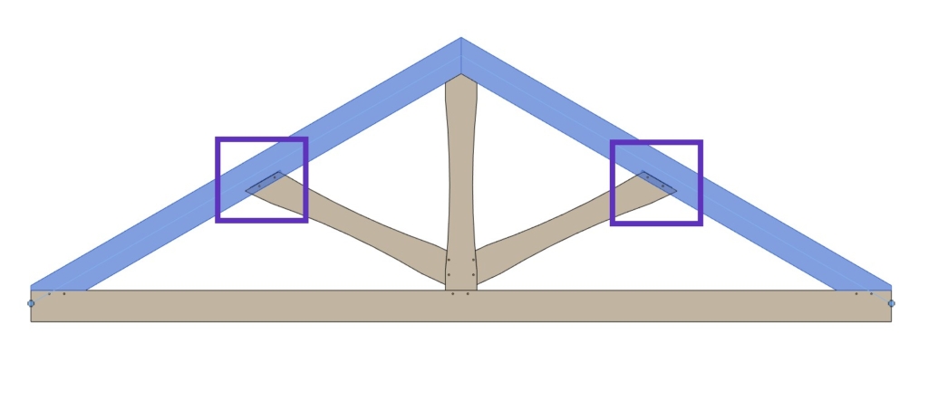
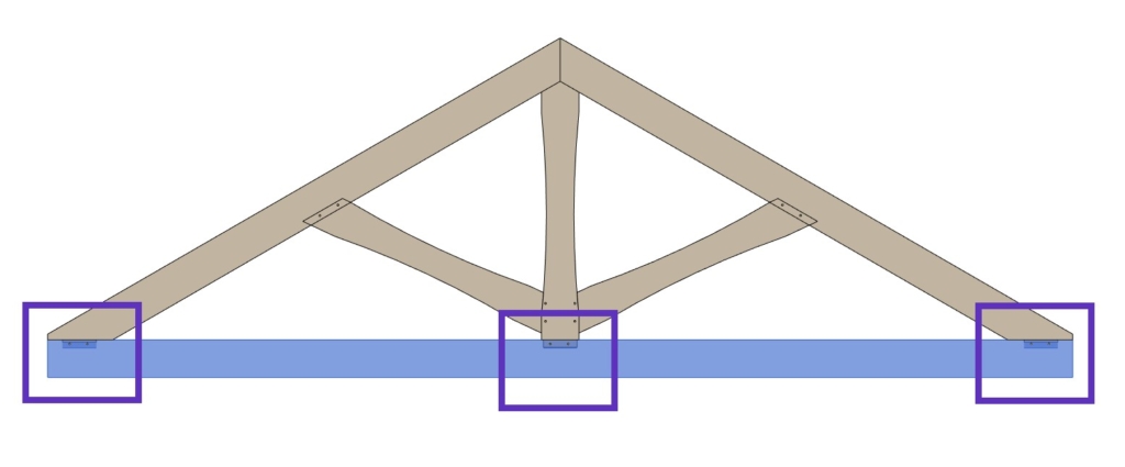
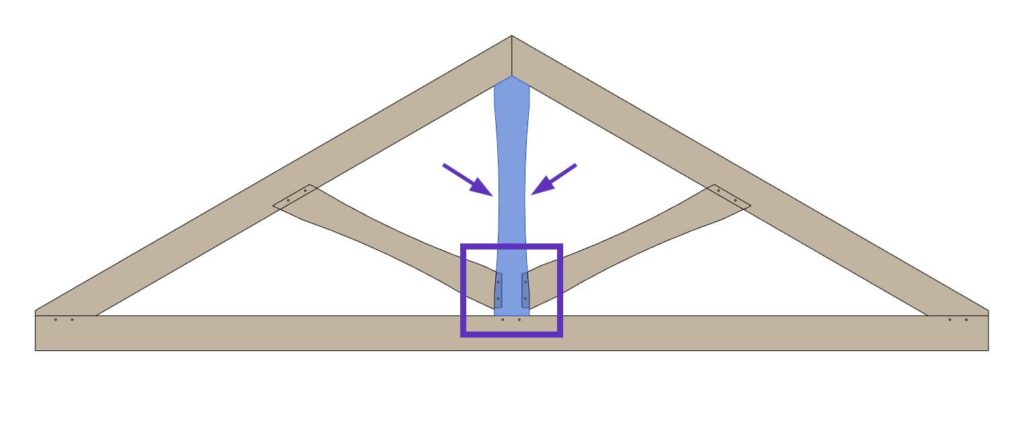
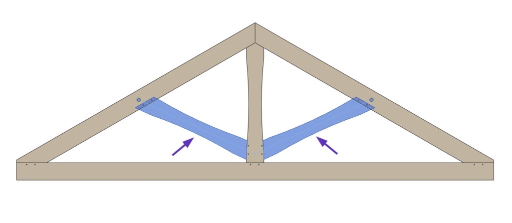
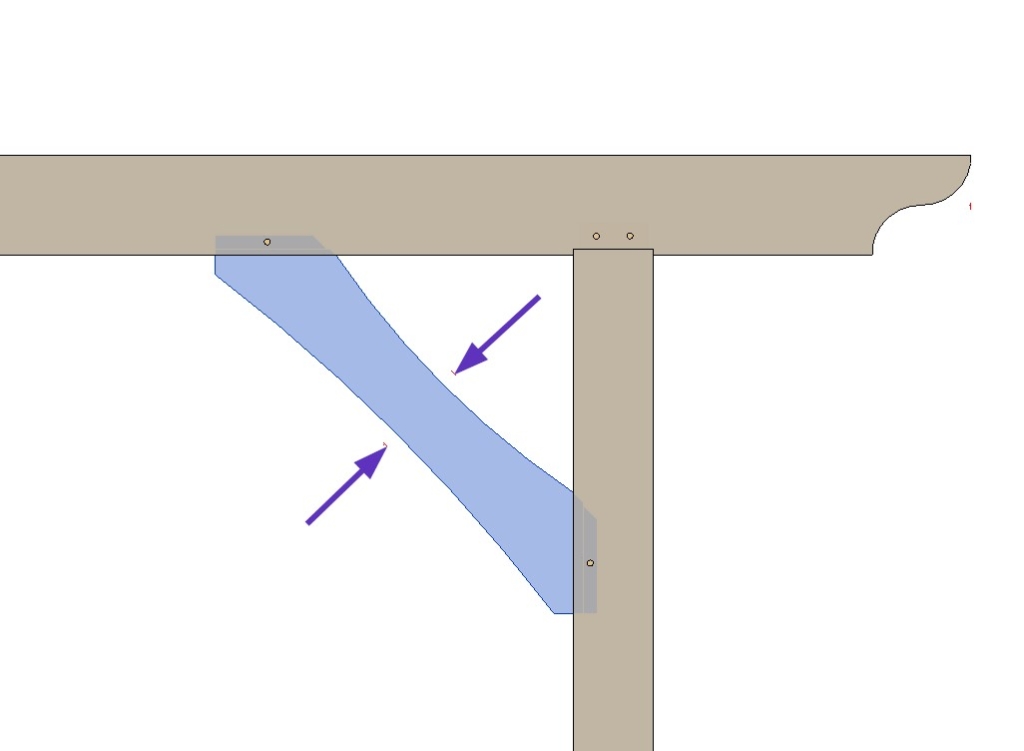
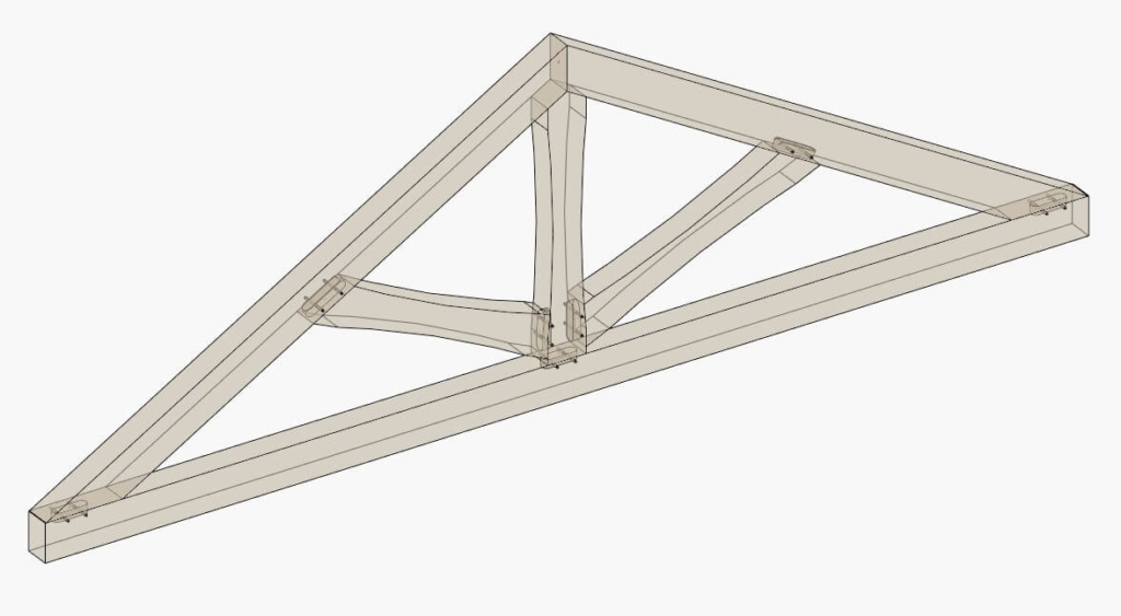
Elements inserted with the Top Chord, Bottom Chord, Vertical Web and Diagonal Web commands:
STEP 10: Finishing (optional)
In the Finishing tab, you can frame additional layers like Secondary Frames, Nailers and Siding. You can also split parts to create Sheathing and Paneling layers.
For example, I created additional layers for battens/nailers and roofing/finish for the roof, and a siding/finish layer for the wall, as you can see here:
As a result, additional layers are created using the Add Nailers and Add Finish commands:
DOCUMENTATION
STEP 11: Number elements
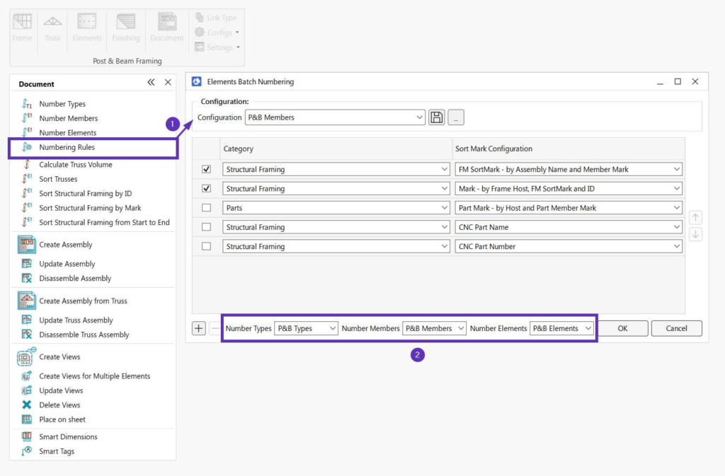
In the Numbering Rules window (1), choose all needed rules for various categories (like Walls, Parts, Structural Framing, Structural Connections, etc.) and their parameters, which should be filled in, in a single configuration. Also, assign configurations that should be used with the Number Types, Number Members and Number Elements commands (2):
Please note, that these sample configurations can be modified to each user’s needs and standards. That goes for all configurations for Framing, Connections, Numbering, Shop Drawings, etc.
Before creating shop drawings and schedules, ensure that all elements are numbered.
Since you used the Number Types and Number Members commands in Steps 5 and 8, respectively, and numbered Trusses in Step 7, when you now number Structural Connections using Number Elements, they will have all necessary information not only about themselves (e.g., FM Sort Mark) but also about their hosts (Structural Framing elements).
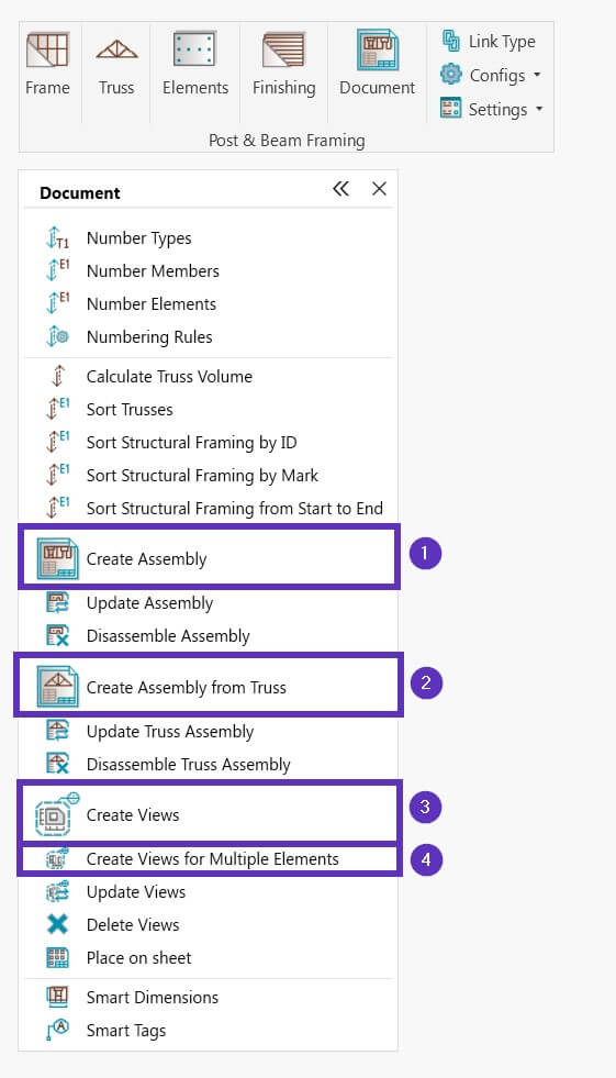
STEP 12: Create shop drawings
When all elements in your project are numbered, you can create shop drawings and schedules and distribute them on sheets. And the software automates all that for you, of course. Simply select an element (or multiple) based on the drawing you need to create, and use one of the commands for creating documentation.
- Create Assembly (1) is for creating assembly views and schedules for Structural Framing, Structural Connection, and other elements.
- Create Assembly from Truss (2) is for creating assembly views and schedules for Structural Trusses.
The features for creating assemblies are useful because you get the benefits of working with assemblies, such as separate drawings for assemblies and easier project documentation.
But what happens when you need to detail individual elements that are already part of an assembly? That’s when these features will help:
- Create Views (3) and Create Views for Multiple Elements (4) are for Revit users who need to make drawings of sections and elevations for any building element, all the way from preliminary design stages through to a detailed design. It could be for a wood-framed wall or window, an elevation of selected walls/floors/roofs, or a section of a particular connection, etc.
In these examples, I selected a brace element and used Create Assembly:
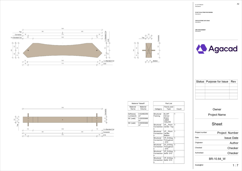
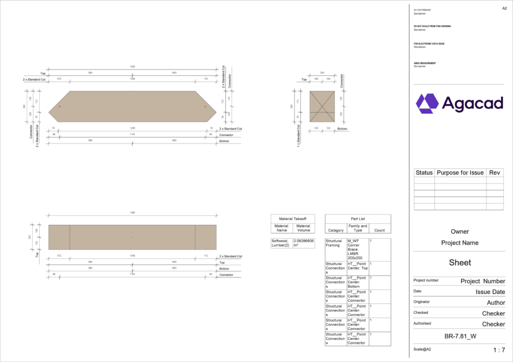
As a result, schedules and assembly views with dimensions and tags were generated automatically and distributed on the sheet.
In this example, I selected multiple elements and used Create Views for Multiple Elements:
As a result, Revit Detail Views with dimensions and tags were generated automatically. These views can be distributed automatically, too, using Distribute Views on Sheet.
In this example, I selected a Truss and used Create Assembly from Truss:
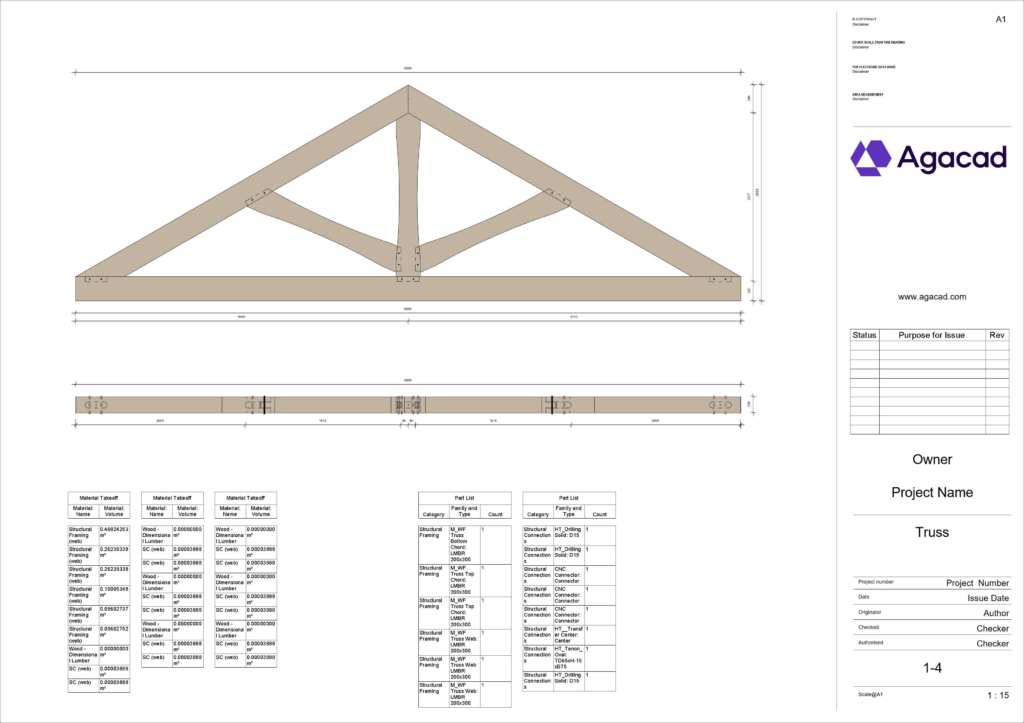
As a result, schedules and assembly views with dimensions and tags were generated automatically and distributed on the sheet.
That’s it! All sample configurations used in this explanation can be found and modified under Configs in top-level menu:
Free trial
Download a free trial of Post & Beam Framing and test the plug-in yourself! Let us know if you’d like to have a personal demonstration online or if you have any questions.
Need to know more about the UI? See this blog post for a complete tour.