This is the third post in our series on LOD 400 modeling for precast concrete in Revit. Part I was about columns. Part II about beams.
Autodesk® Revit® lets you easily model walls for precast buildings. In this blog post we will go over the full workflow for modeling precast concrete walls and generating documentation using AGACAD’s Precast Concrete BIM Solution for Revit.
1. Modeling precast walls
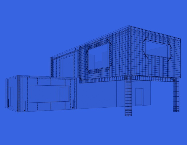
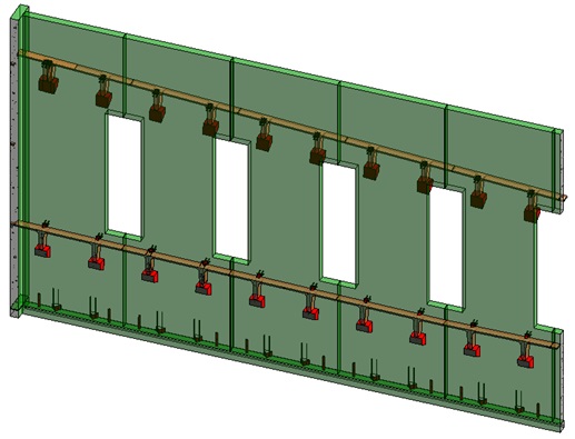
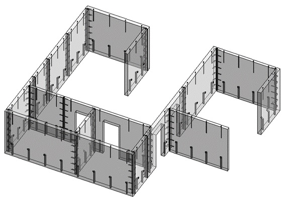
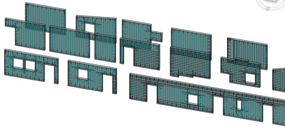
Model precast walls with Revit using standard structural wall system families. Add doors and window families or face-based void families to have openings in the walls. In this stage, draw your walls from corner to corner, not dividing them into separate precast panels. I recommend modeling them with the correct height constraints – from Level to Level, the way they will be built. Later you can copy them into levels above with Revit’s ‘Paste Aligned to Selected Levels’ command.
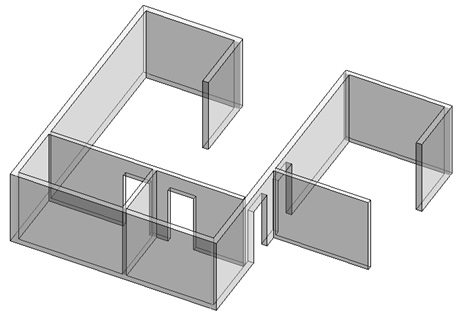
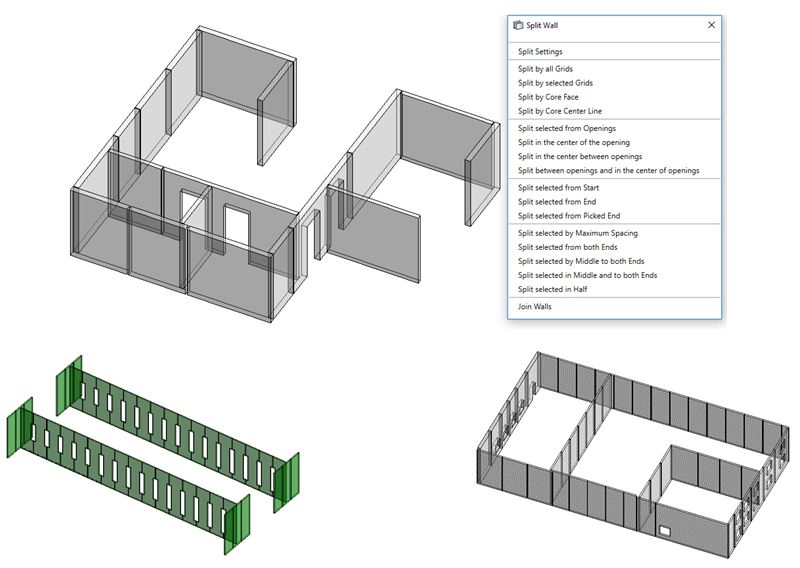
After walls are modeled, divide them into separate panels with requisite gaps between them using the Smart Walls tool that’s part of our Precast Concrete tool set. Smart Walls has wall-splitting functions — by size, by openings, by other walls, by grid lines, etc. — that let you size your panels just the way you need. The tool will automatically disallow wall joins for you, so it’s easier to handle them later.
2. Inserting connections
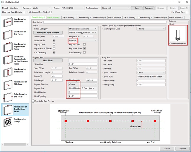
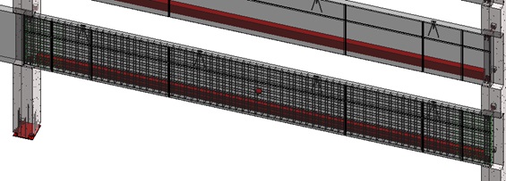
Now that panels have height and width set, go on and model them further to reach LOD 350. Insert cuts, reveals, connection loops, plates, grout tubes, ferrules, lifting embeds automatically using Smart Connections.
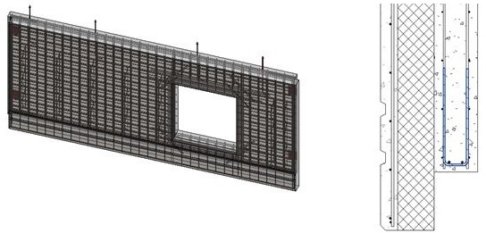
3. Placing rebars
If you’re shooting for production level, LOD 400 is needed. And that means modeling thousands of rebar, which is a major headache. That is, if you’re doing it manually. But if you use our Wall Reinforcement tool, then all that rebar can be created quite quickly.
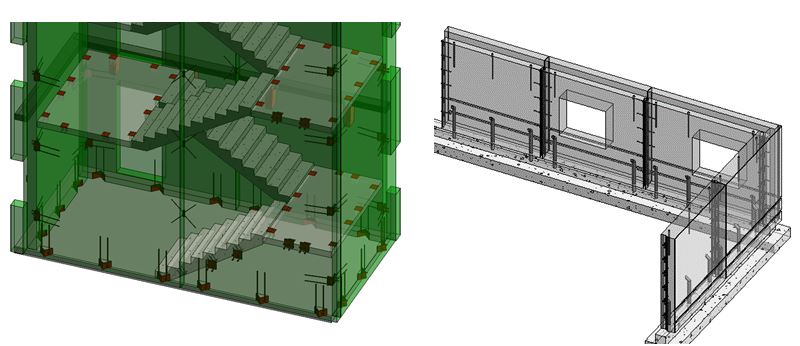
4. Numbering wall panels
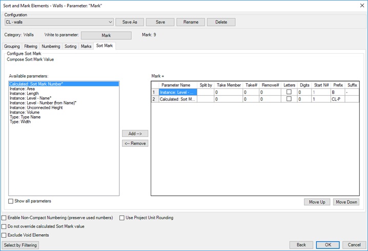
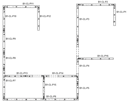
Before making assembly drawings, renumber elements with Sort Mark to have them sorted and marked correctly, by writing information into the instance parameter of each wall.
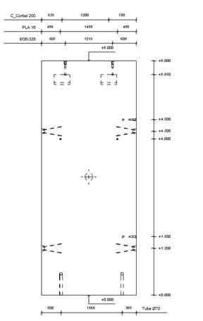
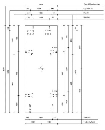
5. Creating shop drawings
Create shop drawings automatically with Smart Assemblies, using the configuration window to define how many views should be created, what should be visible, what kind of dimensions should be created, and how information should be presented in the schedules.
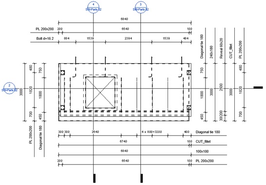
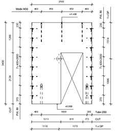
Different dimensioning styles can be used based on company standards.
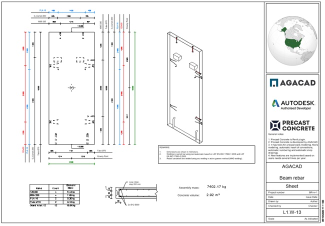
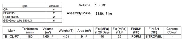
Get schedules with number of parts, volume of concrete, etc. automatically:
Add legends as needed to the sheets in the defined position for each wall panel. These could be 2D views that have to be repeated on many sheets, notes, typical details, etc.

Once the first assembly has been created and the sheet template is ready, all the rest of your wall shop tickets will be created automatically. Just select the number of walls, click ‘Create Assembly’, and shop drawings will be created for all of them, lickety-split.