Our Precast Concrete solution for Autodesk® Revit® users has always been a top-class product for increasing productivity. Autodesk recognized this by naming Precast Concrete as an AEC Industry Partner solution back in 2018. Since then, we’ve only continued improving it, implementing lots of updates and expanding its capabilities according to customers’ needs.
At the end of 2021, our team gathered forces to add many new features that had been requested by clients, so that Precast Concrete would continue to impress current and future users, Arkance Group members, Autodesk, and other partners. The features added were based on a questionnaire sent to current users, past requests from Revit users around the world, and years of development experience.
A massive amount of work was completed in two months, resulting in the implementation of many of the features people had requested. And the groundwork was laid for development of a new UI as well, but it will be released later due to interplay with other products.
In this post, we’ll go through what’s new with modeling and then move on to the documentation side.
Modeling
of precast concrete structures in Revit
Place connections at beam end automatically
This is common in different types of projects, but US clients were particularly eager to have it to place pockets for joists that connect to tilt-up panels, double tee slab panels coming into the bearing walls, etc.
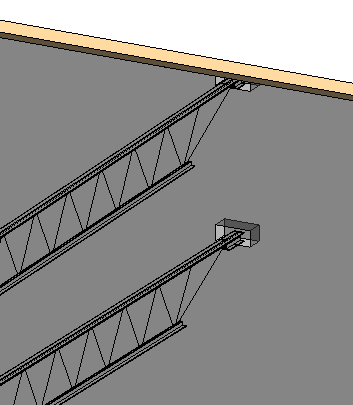
Check out our video on how to make, place, and track pockets for steel joists in Revit.
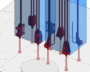
Search up & down columns for connections
We already had many options to search surroundings and place connection families based on that, but clients from Belgium were using a little different workflow that required a novel approach. So now the Column Reinforcement tool opens up even more possibilities.
Here, connections in the column are placed based on bolts in the foundation.
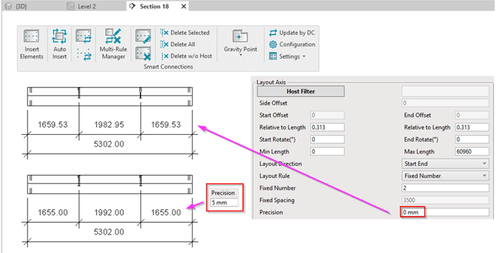
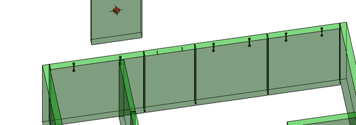
Insert lifting embeds by gravity point of Revit elements
You probably don’t want to deliver a drawing with 1659.53 mm value, but rounding is also not the best way to go about it. So now, inserted elements can be automatically moved based on the precision you use.
(P.S. I hope you don’t calculate the center of gravity manually…?)
Insert lifting details based on Revit element mass
There’s a rule that you can set up in such a way that the appropriate Family would be used for different sized elements. The tool will automatically calculate Element mass before inserting these, so you can use filters and automate this process even more than before.
Create rebar automatically at T intersections
This is useful for cast-in-place as well as precast walls. At wall joins, you typically want to add additional bars in those locations for technical reasons or because of acting forces. And now you can set up this automatic result not only for corners but for T joints as well.

Place rebar by Face
Our reinforcement modules work with solid and sandwich walls, L/IT/rectangular beams, and rectangular and round columns. But what if you have differently shaped elements?
Don’t think about it, just use this feature to place rebar on the selected face, on the face between two faces, or on the face within a defined distance. Use it with precast or cast-in-place concrete walls, beams, or columns.
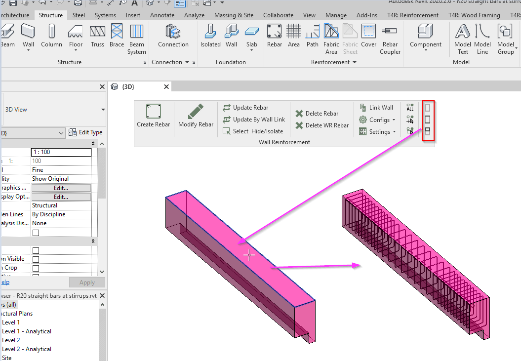
Easily change solid presentation of rebar in 3D view
It’s crazy that such an easy task is so complicated in Revit. Not anymore with this update – change solid presentation for all rebar, selected rebar, or rebars of a selected host.
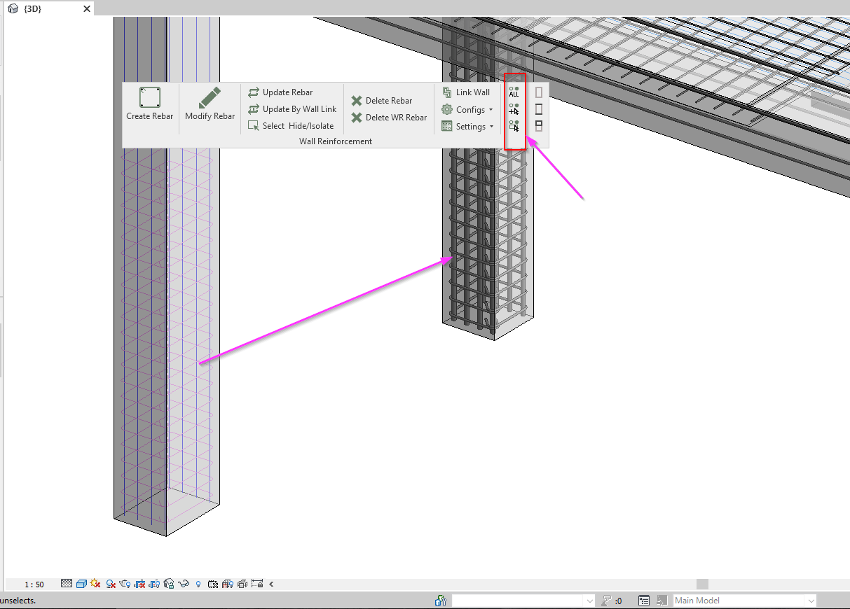
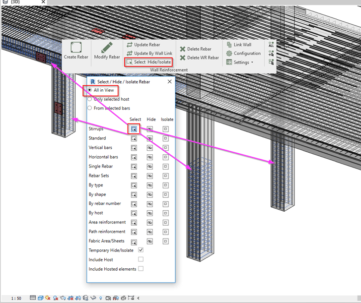
Select, hide, or isolate any rebar easily
Detailed projects, especially those with a lot of overlapping elements, make visual inspection difficult.
Temporarily isolate wall with all its rebar and connection plates? Hide only area reinforcement to be able to check additional bars and stirrups? Hide hosts with rebars that you don’t want to see?
All easy to do with this menu. Try it out, and fear modeling rebar in Autodesk Revit no more!
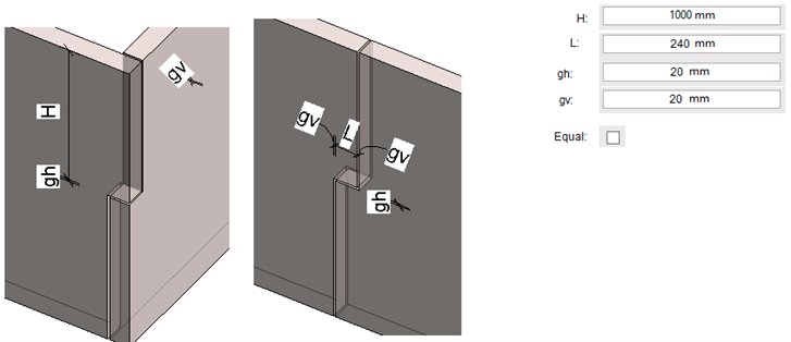
Automate interlocking wall connections
Alright, so this is a special update. While not everybody designs like this, at least people in the Netherlands will know what I am talking about.
Creating an interlocking shape for wall panels to connect takes time. You have to edit the profile, draw the correct shape, leave gaps, go to one section, create another one… and do that for each corner.
No fun.
It’s much better to add settings and apply it everywhere you have corner joints. Then you just modify an individual location and off you go on your merry way with more interesting things to do in Revit.
Documentation
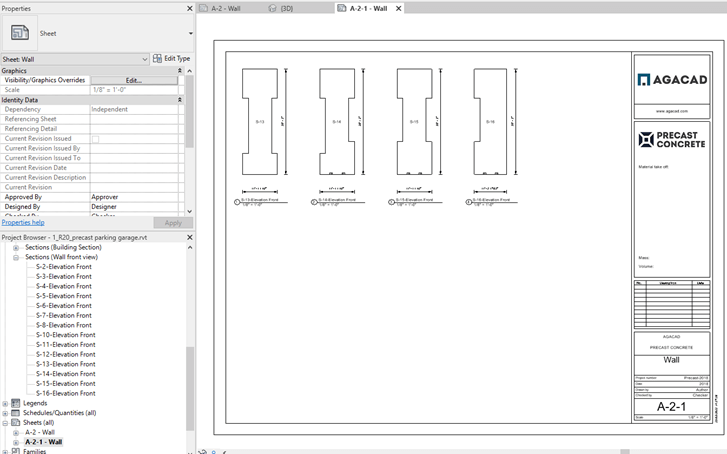
Create isolated, non-assembly views & place them on sheets
It’s crazy how much can be automated in Revit, and how much we can do with Precast Concrete. You can create as many views as you need for any selected element with predefined configuration, and let the tool do the job of cropping views to element size, placing dimensions, and tagging them.
And besides that, you can automatically place any selected views on sheets.
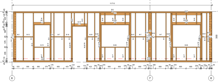
For example, these precast walls or parking garage building were dimensioned and placed on the sheets automatically to provide quick information to the contractor about all wall pieces in the project to plan production, transportation, or provide comments on them.

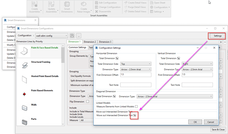
Move small dimensions out automatically
This is one of the annoying things that happens after automatic dimensioning. You have to move out small dimensions to make sure the client can read them. And to do that manually takes a lot of time, so we automated it, so that the tool will do it for you. Just turn this option ON.
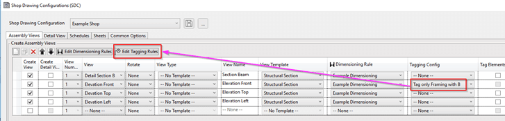
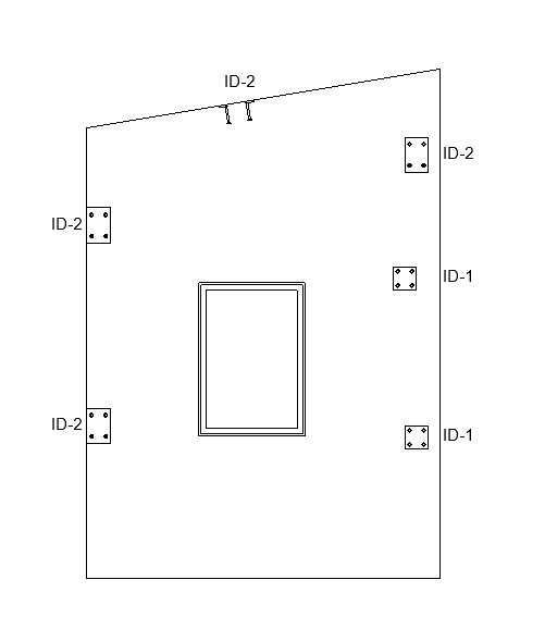
Add tags automatically to shop drawings, apply filters on tag location based on tagged element
It’s not that hard to place tags in Revit. But what if you don’t want to tag everything? Or you want to apply different tag types for different elements? Or, instead of at the center, tags should be at the top left of elements?
Well, now all that is possible in the documentation part of Precast Concrete.
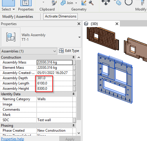
Added size parameters to assemblies
You get size parameters once you create an assembly. Sometimes the host element has size parameters and that’s enough, but what if you have a few in the same assembly, and you want to get overall dimensions?
Yeah, calculate manually and add them to special parameters.
But…while that’s possible to do in Revit, why should you if it’s done already?
Renumber Walls by Revit model line
Numbering is a very quick process with Precast Concrete. But now, numbering by Model Lines give you more control on numbering sequence. For example, tilt-up wall panels should be numbered just around the perimeter – so just draw a model line and run Precast Concrete numbering feature.
Bingo-bango. Done in the blink of an eye. We think you’re gonna like it.

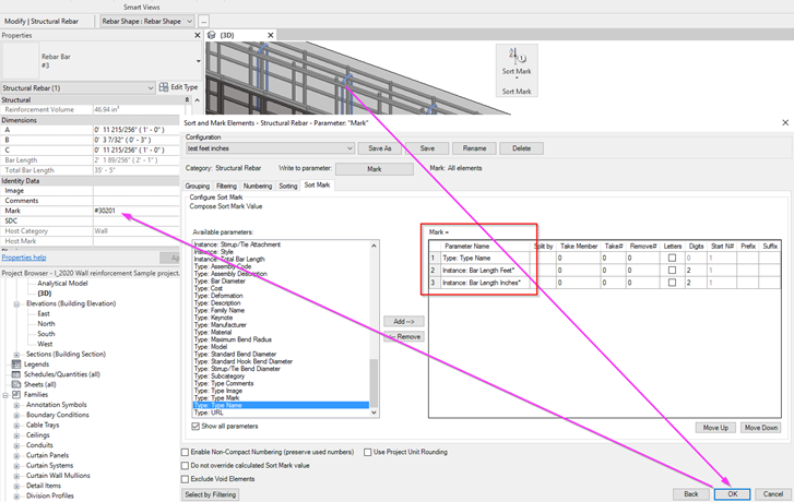
Renumber reinforcement in Imperial projects
Although numbering reinforcement is done automatically in Revit, rebar numbering standards can be different in every structural design office. A common format in the USA is: rebar number, shape or diameter + 2 digits for feet and 2 digits for inches, without special characters.
Imagine, you have a lot of different shapes and lengths of rebars in a given project, so entering this information manually takes time and is quite easy to make a mistake.
But not with Precast Concrete.
Prepare your configuration once, and run through the numbering process of reinforcement lickety-split.
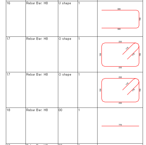
Create rebar images with length values of each segment
There is an option in Revit to use schematic images and use A, B, C values for rebar shapes in schedules. Though it might look ok… let’s just say it’s not for everyone.
I remember we started getting this request. First it came from Germany, then Dubai, Brazil, Belgium, the Netherlands… we had no choice. Like our Belgian partner said, “It’s a must.”
So now you can change line color, text and image size, and make your rebar schedules shine.
We’re quite sure that Precast Concrete is one of the most powerful options on the market when it comes to BIM design software, giving Revit users -structural engineers, drafters, modelers, and detailers- a perfect alternative to Tekla.
With this solution on top of a great BIM platform like Revit and trusted partners like AGACAD, you can design precast concrete structures with confidence and less stress.
Free Demo
Before you take a trial of Precast Concrete, we encourage you to get a free personal demo with our BIM application engineer. That way, you’ll go into your trial period with a better idea of how to use it and already have answers to your preliminary questions.
Free Trial
To start a free trial of Precast Concrete, download our TOOLS4BIM Dock for your Revit version.
Learn about modeling rebar automatically in our free live webinar on March 10, 2022.