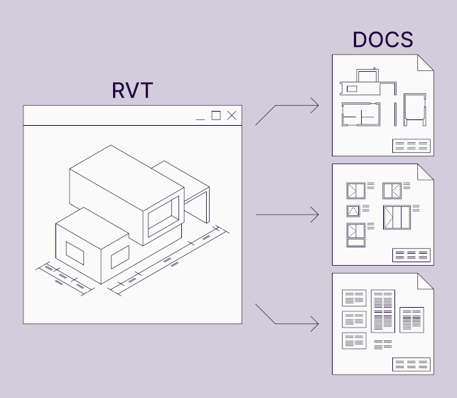
Generating drawings and completing other project documentation can take a good chunk of time even when you have a well-prepared Autodesk® Revit® model. Placing dimensions and tags, marking elements, creating legends, generating views and sheets can all be automated with Agacad’s newest product – Smart Documentation.
As an MEP engineer, I know how time-consuming it can be to properly document a Revit model. So, in this blogpost I’m going to show 9 ways you can speed up the project documentation process and improve the overall quality of your Revit projects.
But first, a short intro about the productivity toolset itself.
What is the Smart Documentation Revit plugin?
Smart Documentation was created by combining some of the functionality of 6 of our other tools into one product. It automates the fundamental annotation features of Revit – dimensions, tags, legends, views, and sheets – and also provides additional value through features that aren’t in the out-of-the-box Revit, like element marking, data extraction, QR code generation, and Excel spreadsheet import.
It works by configurations that can be saved and used later, meaning that you only need to create the logic once, and then all the work will be done for you automatically in the future.
In this blogpost, I have tailored my examples for MEP engineers, but our software can just as easily be used by architects or engineers of other disciplines.
Also, I’d just like to note that the examples shown below are only a small fraction of what the add-on is capable of. Smart Documentation works with elements of most Revit categories and has many settings to help automate lots of unique scenarios.
Without further ado, here are 9 MEP project documentation tasks done automatically in Revit using Smart Documentation.
1. Dimensioning Elements
Drawing creation often begins with placing dimensions. There are 2 ways to dimension elements using Smart Documentation: Predefined Dimensions and Quick Dimensions.
Predefined Dimensions allows for large-scale dimension placement for elements in a view. It has a function that lets you dimension all families to the closest structure (Wall, Floor, Roof, Column, or other), to Levels, or to Grids. And that works with linked elements as well.
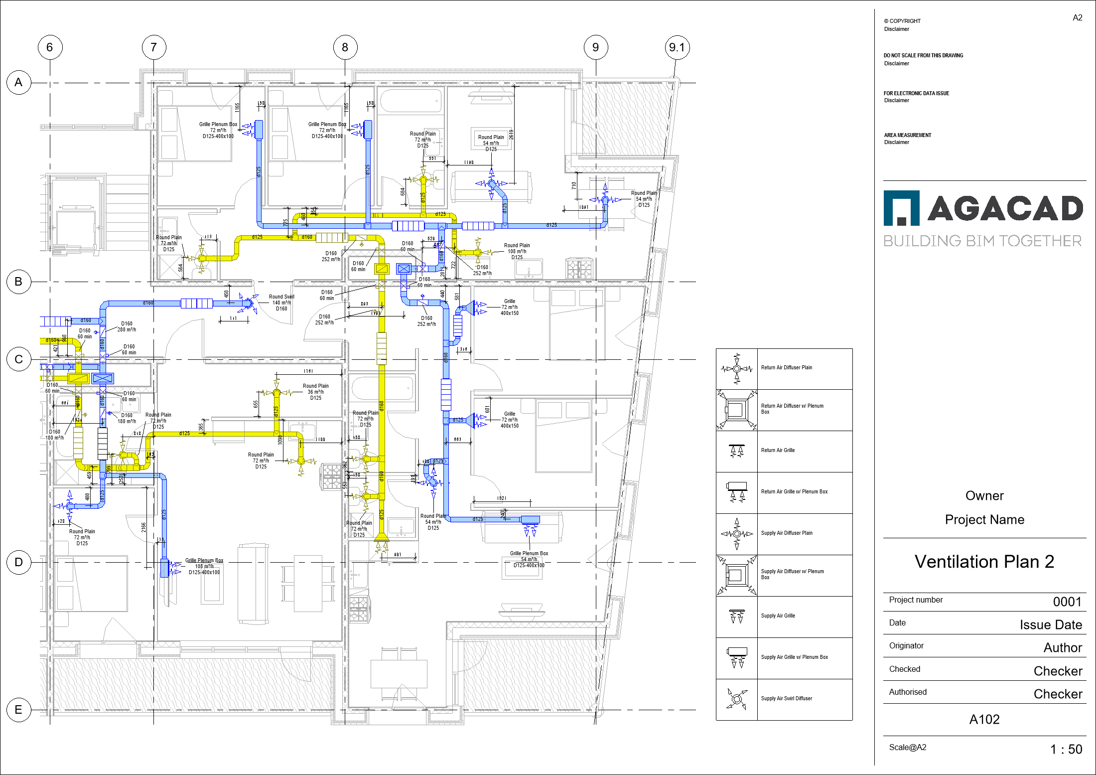
Here, I’m running a configuration that places a horizontal and a vertical dimension to the closest wall for every Air Terminal. When the Air Terminal is flush with the wall (bottom left air supply grille), only one dimension is placed.
Not only can Predefined Dimensions place dimensions to the closest structure, but it can also place dimensions between elements. In the example below, I’m dimensioning the openings for the MEP services. (Those elements were inserted using our Cut Opening Revit plug-in.) With Smart Documentation’s ‘Dimension Selected Elements’ command, I get the sizes of the openings and the distances between them. And in case the dimensions are very close to each other, they are automatically moved out.
Keep in mind that the above use-cases are just a few ways of using Predefined Dimensions. It is very flexible and allows for automating dimensions in just about any scenario.
The second mode for dimensioning elements using Smart Documentation is Quick Dimensions. It’s for creating dimension chains between selected elements.
In the view below, I have dimensioned all the ducts with just a few clicks.
2. Placing Tags
Smart Documentation has a function that allows you to tag elements in batch. In contrast with Revit’s ‘Tag All Not Tagged’, Smart Documentation lets you use multiple different tags for same-category elements. To do that, you have to create rules to which filters can be applied. You can also specify offsets and tag position, leader or no leader, and automatically move tags when there is an overlap.
I’m using the same view as before, and I’ve tagged all the ducts in the view in 2 clicks. And I was using 3 different tags: one for insulated round ducts, another for insulated rectangular ones, and yet another one for uninsulated ducts.
3. Creating Views
Not only does Smart Documentation let you create views for selected elements automatically, but it allows you to combine those automated views with your tagging and Predefined Dimensions configuration.
And that means your newly-created views come already tagged and dimensioned.
Talk about a time-saver.
For MEP engineers, this functionality can be especially useful for creating piping spools.
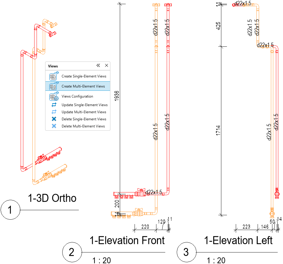
All the views above were created simply by selecting a piping run and using ‘Create Multi-Element Views’. Down below, I’ll show how selected views can be automatically placed onto sheets (see #9).
4. Marking Elements
Frequently, you have to mark elements in a specific order in projects. Could be mechanical or heating equipment, plumbing fixtures, etc. Doing all that manually takes a lot of time, and if a new element is inserted in the middle of a queue…well, then half of the marks need to be rewritten.
Smart Documentation’s ‘Element Numbering’ allows you to construct any marking format and use it on large number of elements at once. It can also extract data that is otherwise invisible through the Revit interface.
In the image above, you can see a snippet of an apartment building’s heating plan. All the heating equipment for the entire project was marked in just a few seconds. And the logic was that the marking restarts at every level (and writes a prefix with the level number, e.g. – “L-4”) and follows the room numbering order by reading the data of the room in which each element is placed.
And that’s just one example of a marking rule. You can make pretty much any custom rule for marking. And if needed, elements can also be marked one by one, simply by clicking on them.
5. Extracting Elements’ Coordinates
As mentioned, some data is invisible in plain Revit, but it’s still possible to extract it. A good example is coordinate values.
For MEP engineers, coordinates can be needed when working with underground drawings.
Using ‘Auto-Fill Coordinates’, values are filled into the specified text parameter to be visible in views. Both the Project Base Point and the Survey Point coordinates can be used.
If a custom format of coordinates is needed, the same can be achieved with ‘Element Numbering’, but there you can also specify the prefixes and suffixes.
To do all that in plain Revit, you would need to use Spot Coordinate for every element. With Smart Documentation, all that is done automatically, and the values are also stored in a parameter so that they can be exported to other software, if needed.
6. Generating QR Codes
This probably isn’t in your typical documentation preparation process, but it’s worth taking a look at it because it can improve communication between the design and construction phases. QR codes can be used for tracking materials on the building site or for providing additional information in a simple form.
In the configuration, you can predefine parameters, whose values will appear in the QR image when it’s scanned. And then you can generate large amount of these images at once.
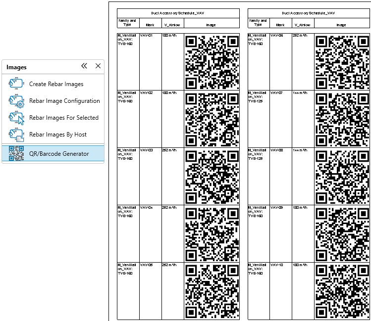
QR codes are placed in an image-type parameter. And these images can be seen in Revit when a schedule is placed on a sheet.
7. Creating Legends
For your drawings, you might also need Legends. The standard way most engineers go about it is sketching the whole table by hand and then manually placing all the Legend Components and text fields.
Here’s another way.
Using Smart Documentation’s ‘Create/Edit Legend’, all you need is a base for a table – so that the software knows where to place text fields and Legend Components. Then you create your own list of elements to be in the Legend, and the rest of the table will be generated, replacing text fields with the specified parameter values.
This functionality can be used for more than just Legends. It can create tables with images using parameters from a family, calculate totals, and quickly update data when changes are made. Tables can be either vertically or horizontally listed, split into smaller tables, and can work with linked elements, too.
An example of such a table can be seen below (section #9) where I created a specification of hangers and supports used in a project with quantities for every size.
8. Importing Excel Files
Sometimes in a project you might need data that isn’t in your Revit file. That could be, for example, a table that you want to have in your Sheets.
Smart Documentation can import Excel spreadsheets, including style settings, into Revit as Drafting Views or Legends.
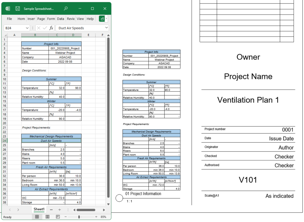
After import, the link between the Excel spreadsheet and the Revit file is maintained, meaning that you can see if any changes to the document were made and update if needed.
9. Creating Sheets & Placing Views
Now that my model views are dimensioned and tagged and I have my Legends, it’s time to create sheets and place views.
Smart Documentation has two ways to go about that. The first is Distribute Views on Sheet. It will create as many sheets as needed to place the selected views with the specified offsets between them.
In the image below, multiple tables (that were generated using the workflow in section 7 above) were placed on sheets using ‘Distribute Views on Sheet’.

The other way sheets can be created is according to a Template Sheet. This can be very useful for multi-level building projects. Simply select the views to be placed on sheets, and map them to the views in the template.
Trusted tools for Revit project documentation
As you can see, by automating Revit’s manual, labor-intensive annotation processes, Smart Documentation drastically cuts the time required to properly document Revit models. No more placing dimensions, tagging elements, creating views and legends, and placing them onto sheets by hand.
At least, not if you have Smart Documentation in your toolbox.
To add to that, Smart Documentation also provides additional documentation features that you won’t find in plain Revit: element marking by preset rules, data extraction (room/space data, coordinate values), QR code generation, and Excel spreadsheet import.
Keep in mind that although all the examples I’ve shown here are relevant to MEP engineers, our software is also relevant to architects and engineers of other disciplines.
Want a visual of what I’ve written about in this post? Check out the recording of our recent webinar: