You can now frame walls faster, better and more easily thanks to a new improved user interface for Agacad’s Wood and Metal Wall Framing software and several other valuable new features.
A more intuitive interface
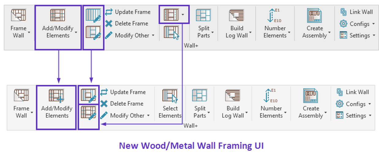
We’ve simplified and enhanced the UI for these two popular wall-framing toolsets for Autodesk Revit. Their fresh design, style and arrangement are both more visually appealing and more intuitive, empowering users to streamline project workflows and improve all related processes.
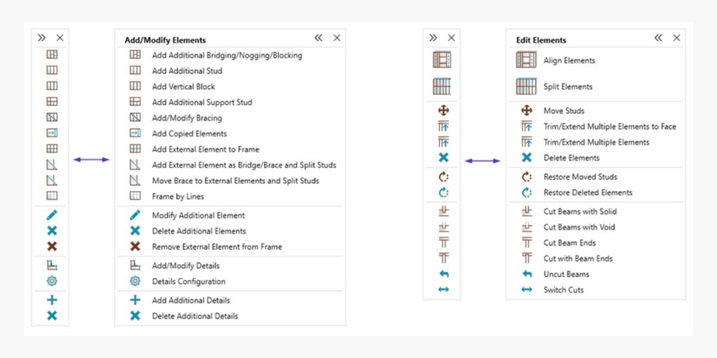
Specifically, we rearranged certain functionality into two floating windows with icons, so users can understand and navigate the toolset more easily. These windows consolidate all the essential features for adding, editing and modifying elements. Users can minimize them to save working space and avoid clutter. We also combined the ‘Modify Frame’, ‘Modify Opening’ and ‘Modify Wall Join’ options into a single ‘Modify Frame’ feature that works based on what is selected.
The images below show details of some of the changes, which we then discuss in more detail.
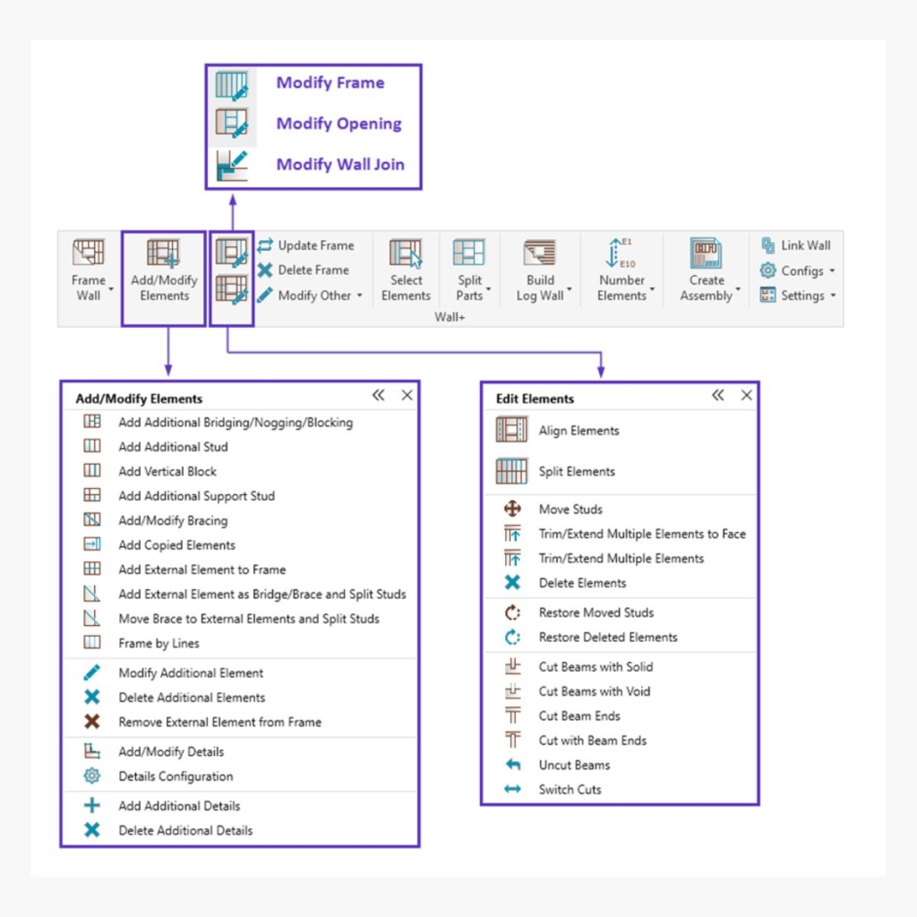
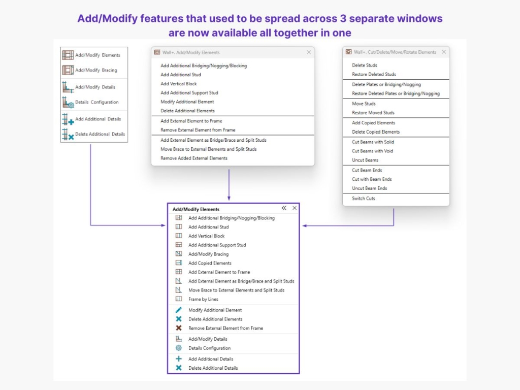
Add/Modify Elements
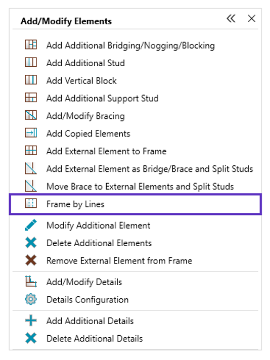
The Add/Modify Elements section has features that let users add and modify additional, copied, external or bracing elements as well as details. Where previously users had to navigate three separate windows, now they can perform all these actions within one unified window.
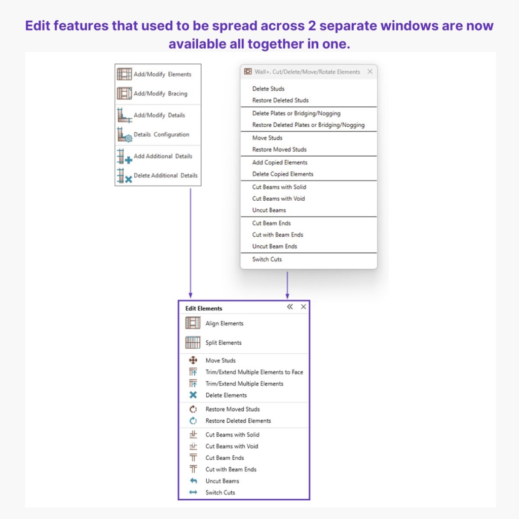
Edit Elements
This section puts the features for editing existing elements together in one place: Align Elements, Split, Move, Trim, Extend, Delete, Restore, and Cut Beams. Previously these features were spread over two different windows. This consolidation simplifies workflows and saves users valuable time.
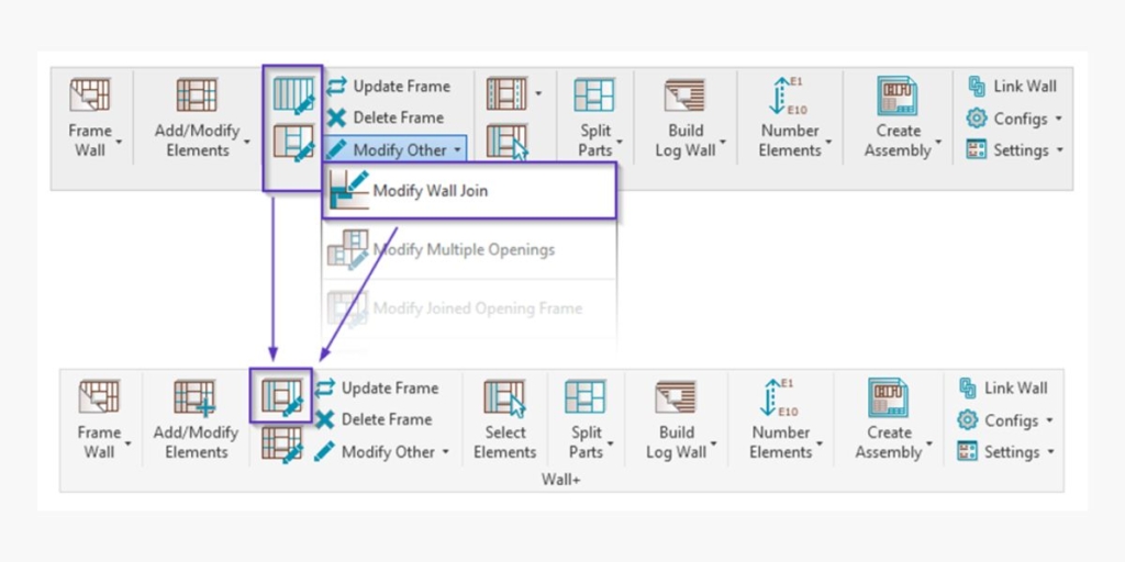
Modify Frame
Now when you enable the Modify Frame feature and select a specific element, you are automatically directed to the corresponding tab within the Modify Frame, Modify Opening or Modify Connection menu. This eliminates the need for users to manually navigate to the needed tab. They quickly access the specific settings and options relevant to their current task for more efficient and intuitive editing.
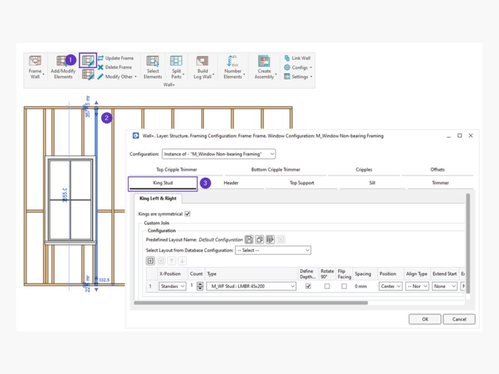
| Modify Frame → select Common Stud → opens previous ‘Modify Frame’ window (and ‘Vertical Stud’ Tab) Modify Frame → select King Stud → opens previous ‘Modify Opening’ window (and ‘King Stud’ Tab) Modify Frame → select Side Stud → opens previous ‘Modify Connection’, etc. |
5 more new features and enhancements
The Agacad Wall Wood Framing and Agacad Wall Metal Framing toolsets have several other enhancements as well, which we now detail.
1. Frame by Lines
The brand new “Frame by Lines” feature significantly broadens your options for frame creation and part splitting. You can now use model lines as references for creating frames or splitting parts.
Model lines can be drawn in any pattern on a wall. For example, you can explode imported CAD file lines obtained from architects, designers or engineers and convert them to model lines. Then you can use the lines as a reference for creating framing elements or splitting parts.
So this feature lets you achieve unique, customized results more efficiently, further streamlining your design process.
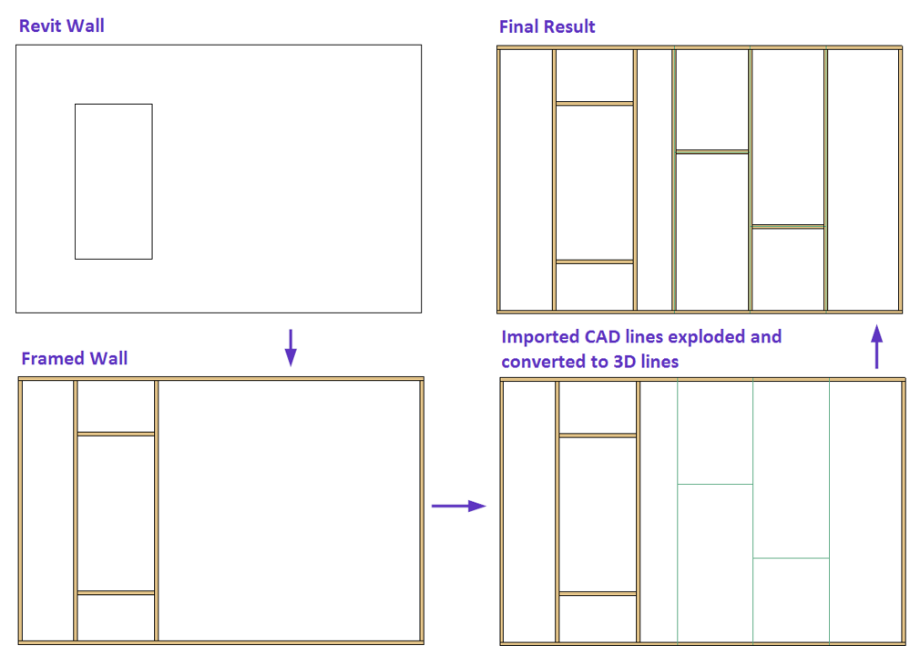
When using CAD lines as references for framing, it is important to follow this workflow:
- Model a wall in Revit.
- Frame the wall with top/bottom plates, end studs or openings.
- Import CAD lines onto the wall finish surface. Set a work plane beforehand in Architecture > Set Work Plane.
- Explode CAD lines and convert exploded lines to 3D lines.
- Frame wall using Frame by Lines (pick a framing element and then select lines for a wall).
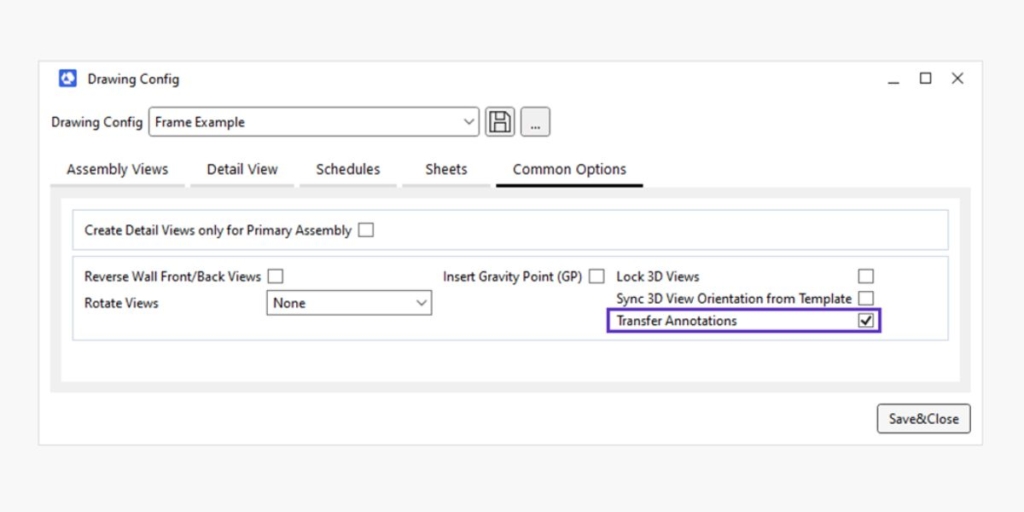
2. Enhanced “Transfer Annotations”
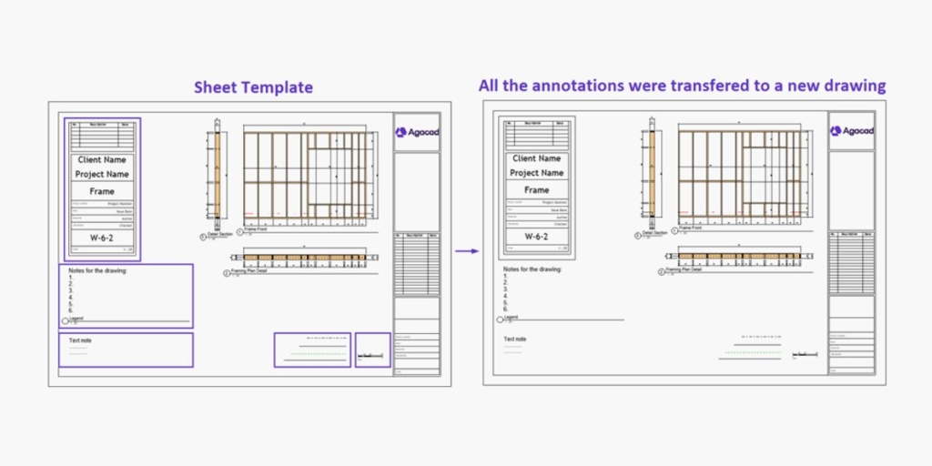
We have significantly improved the “Transfer Annotations” feature. It now includes the transfer of Text Notes, Generic Annotations, Detail Lines, and additional Title Blocks from the Sheet Template. That means more versatility and customization when creating shop drawings.
This enhancement empowers you to create detailed and highly personalized drawings, tailored to your specific needs.
3. Visible Framing Layer in Drawing Configuration for 3D views
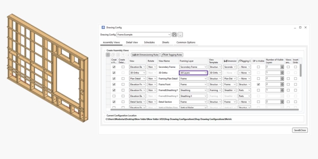
You can now select the visible Framing Layer in Drawing Configuration for 3D views, i.e., you can choose which layers to see in 3D Ortho view drawings. You may want to display all layers for a comprehensive overview or focus solely on the Frame layer for a more specific representation. The choice is yours.
Here’s an example with All Layers selected:
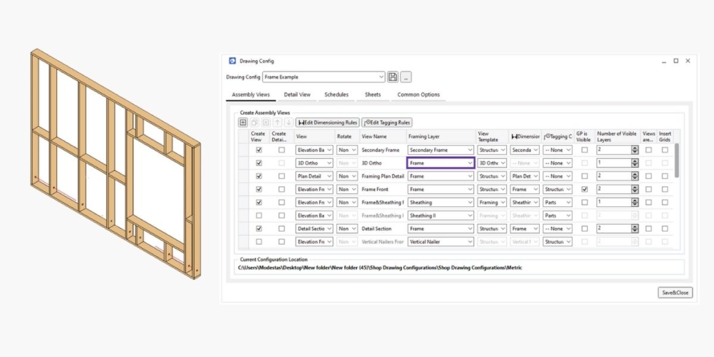
Here only the Frame layer is selected:
4. Checkbox to exclude contour lines for openings
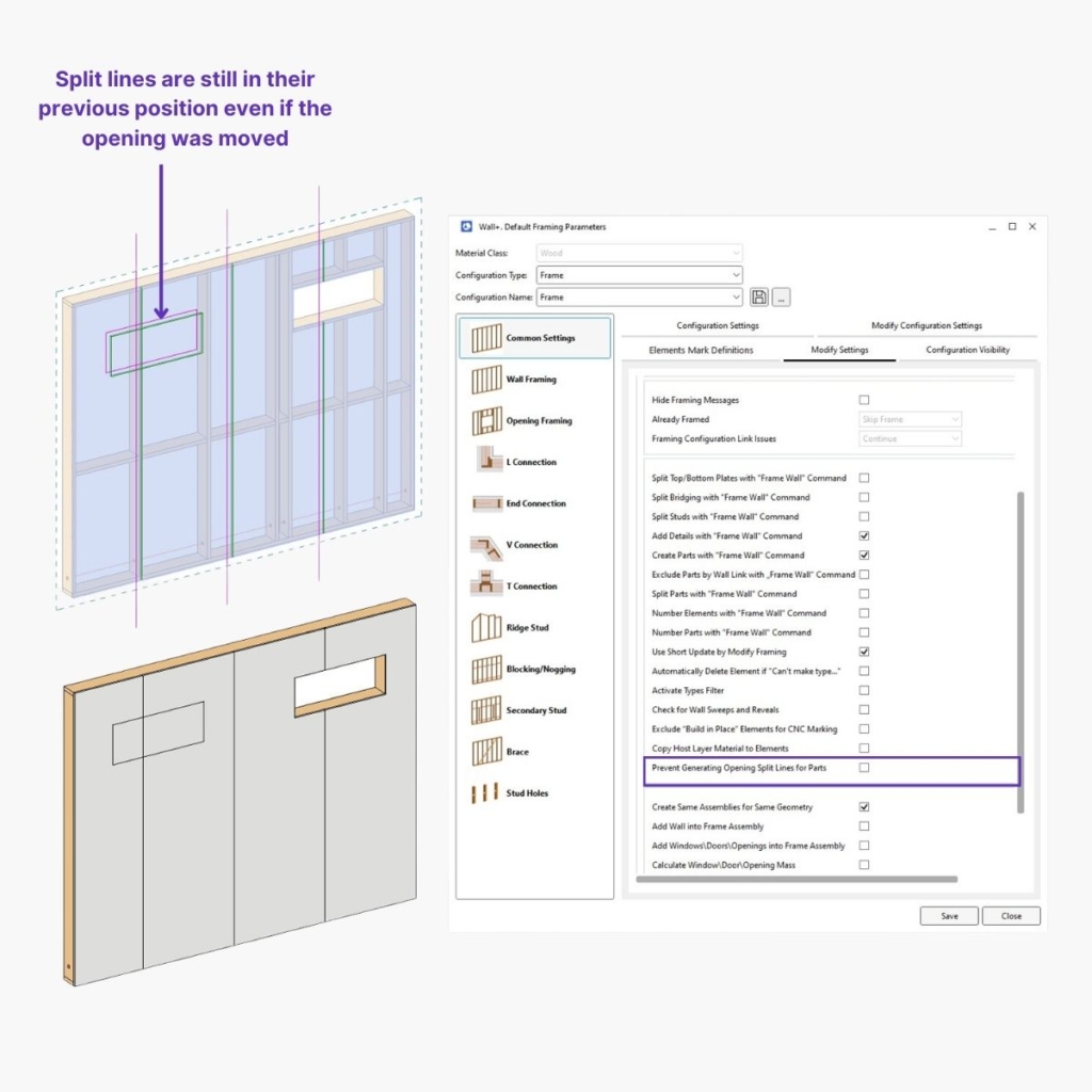
When the location of an opening suddenly changes, split lines may remain in their previous position and parts may have to be additionally merged. To improve this process, we’ve introduced a “Prevent Generating Opening Split Lines for Parts” checkbox. That lets you exclude the creation of the contour for an opening, saving time and effort.
Here’s an example of when this feature is turned off (opening moved, split lines still in previous position):
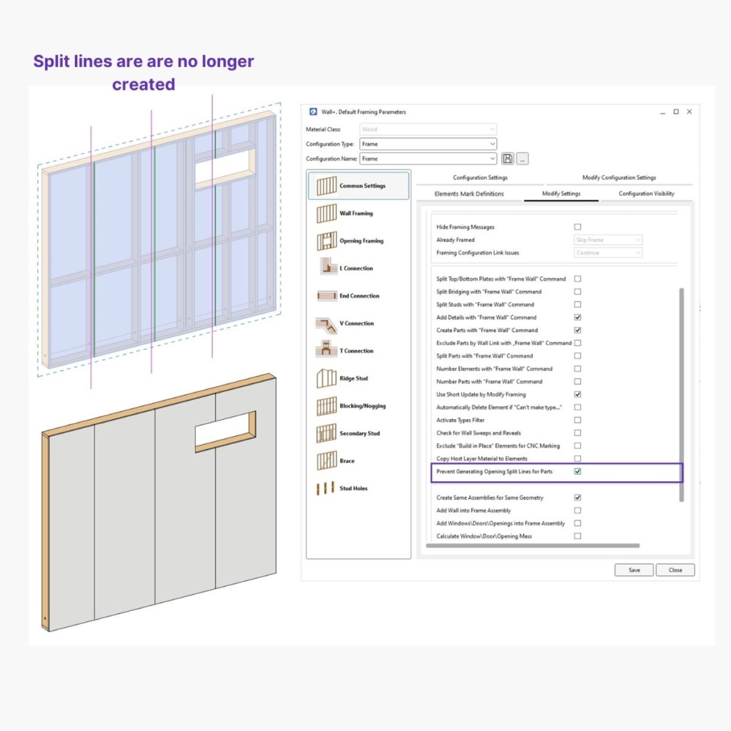
And here’s an example when the feature is turned on (opening moved but split lines not created):
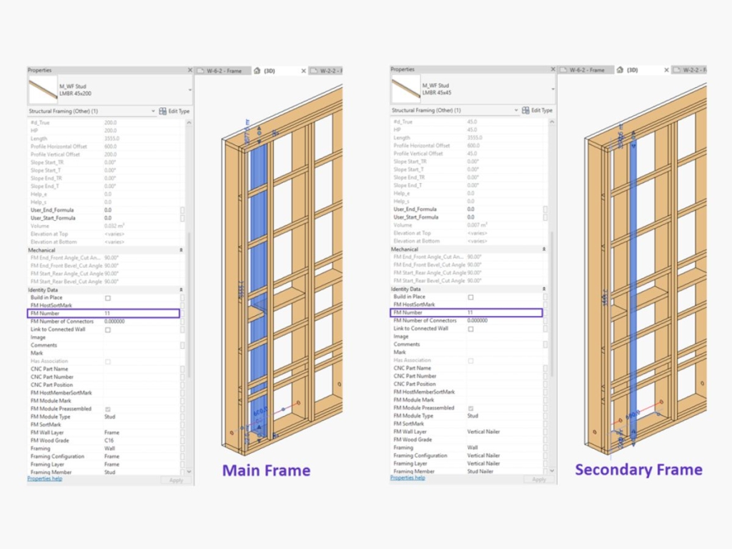
5. Copying of FM Number from Main Frame to Additional Layers
This functionality allows users to delve into more complex framing scenarios with ease. Before using it, make sure that “Align with Main Frame – Adjust Each Stud” is turned on.
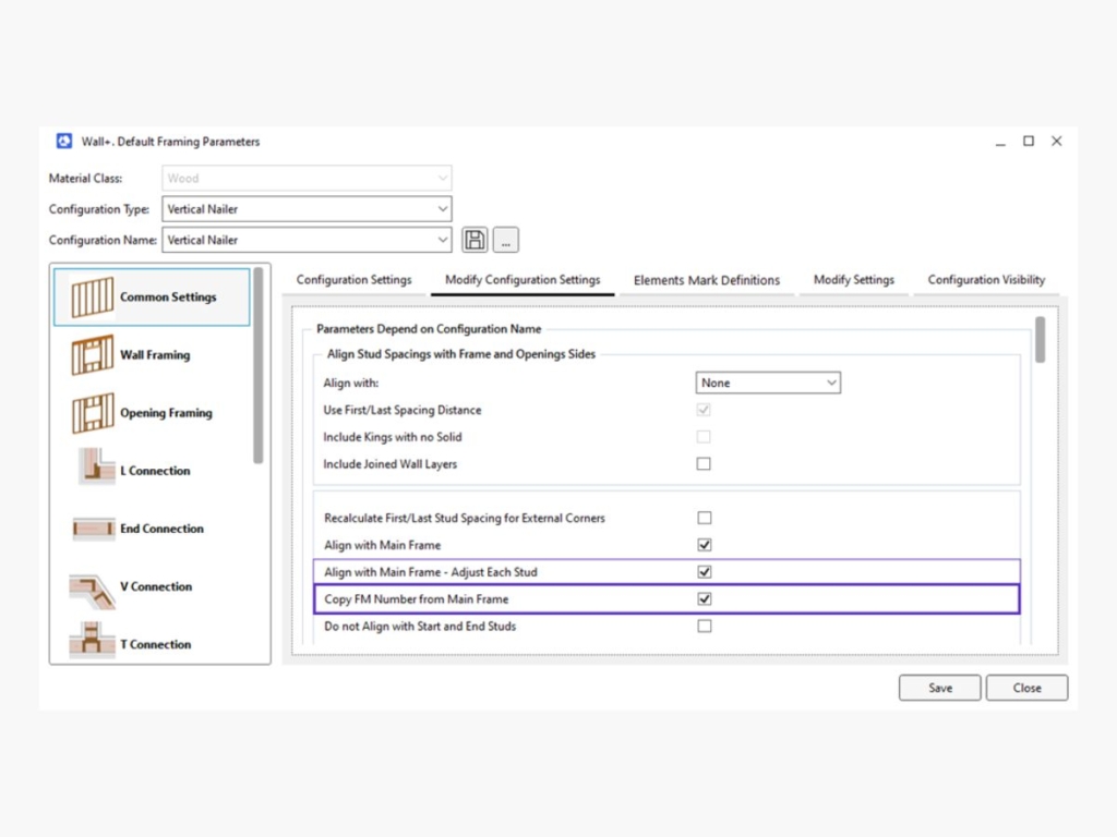
When “Copy FM Number from Main Frame” is activated, all additional layer elements aligned with the main frame will inherit its FM Number value. This streamlines the process of assigning FM Numbers to multiple frame layers, helping to ensure consistency and accuracy in your projects.