
Introduction
As you already know, company AGA CAD is developing productivity-enhancing add-ons for Autodesk® Revit® users. BIM solutions and extensions, in our company, are distributed both directly and through representatives, which we have around the world. We are happy that our reliable partners have excellent knowledge of represented AGACAD TOOLS4BIM products, and some even share their experience in articles describing our product capabilities.
This time we want to introduce our partner’s from Poland, PROCAD Company, article about our BIM solution Insert Elements that was successfully used with steel structural connections to build wooden structure. An author of this article is Andrzej Szumilas, an experienced CAD/BIM Specialist from PROCAD. Thank you Andrzej for letting us republish your post!
So here is the article for your attention:
The Use of Accessories & Fasteners in Wooden Structures Using Insert Elements

When we increase the level of development (LOD) of BIM model, by expanding it with more details such as structural connectors and other accessories, we face a dilemma. Even with repetitive use of structures and inserting 3D components, which are detailing project, will take a lot of time, on the other hand, there may appear a need to count the amount of elements used in the design, graphic presentation and analysis of the feasibility of connectors. For that exact purpose Revit users can use Revit application Insert Elements. At the same time it will help insert many structure connector families, which were built earlier, into appropriate place, such as, walls, columns and beams. Using predetermined rules tools for Revit hook into families based on the surfaces (Face Based) from the categories of structural elements, mentioned above.
Preparing for work
„Experimental training ground” will model the pergola’s surrounding part of the building and protecting the terrace. The wooden construction will stay equipped on corner connectors, brackets beams and columns brackets. The existing structure has been created based on beam systems that are based on the pillars established in the grid axes. For efficient work consider making duplicate views, the best way to go would be using the views from the assigned templates.
Fig. 1 Fragment of a building and an isolated view of a wooden structure
Next, we go to library of Families, which we use for insertion into the structures. Families have to be generally based on the surface (Generic Face Based Family), which had changed category due to being edited for structural fasteners (Structural Connections). Depending on the complexity of the geometry, a DWG file can be imported, or you can create one by yourself.
It is important to note that the family will be inserted on the face of the beam or column, and its location can also fall on the other side of the wall, which is symbolically represented as a gray block in the figure below. Everything depends on the method of attaching the connector on the parent object. Some of the families should stay created in such way that would allow you to easily change the dimensions of the connector, nesting family components inside the main family helps. Some of these families’ components, such as brackets fixed on two sides should be set to Shared Family, so that it could be compiled separately in the Project.

Fig. 2 Ways of positioning and shaping of Structure Connector Families
After loading selected families from the library, we can proceed to insertion of connectors into the elements of design. The following examples show only the principle of operation based on a single element. In fact Tools4Revit allows you to select the whole set of components from a category and insert them into related elements.
Related elements – Structural column
In the model, select the components in the category of Structural Columns and select „T4R: Create and Modify>Insert Element>Insert Element to Related Objects”. We select the related elements and choose the embedding rules for them. We can set different connectors for column’s lower and upper parts – they will both be added at the same time.

Fig. 3 Rules are selected for Families inserted on upper and lower parts of the Structural column
Related elements – Structural Beam
After completing previous steps repeat the procedure. Now we select category of Structural Beams. The rule, which we are using now, places the Structural Connectors at the start and end faces of the beam. This is due to the construction of structural beams, which is a linear object.

Fig. 4 Rules are selected for Families inserted in Structural Beam
Our construction is already equipped with accessories. But what to do if some of them do not correspond to the objectives of our project?
What to do when the connector is pushed deeper along the axis of the beam?
Anticipating such situation we should equip Connectors’ Family with parameter that control the distance from the wall, on which it is nested. It is best, if the parameter used is Instance Parameter. We should remember, that the parameter and geometry controlled by it is pinned to Reference Plane.

Fig. 5 Offsetting Connector from the surface of its nesting wall using Element Parameter
Is it possible to automatically adjust the size of the connector to the cross beam?
Yes, it is possible. You just need to create parameters in Connector Family with exactly the same corresponding name as the crossing structural element, set them as Element Parameters and put them in the Model Properties group. When inserting such element Insert Elements adjusts it to the host element.

Fig. 6 Setting parameters and their grouping for automatic adjusting of dimensional linked elements
What if the beam has different connectors on its ends?
In such case, simply select the required connectors and replace them on the List of Type Selector.
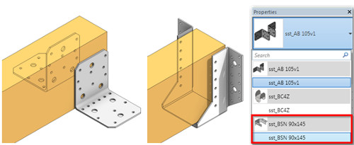
Fig. 7 Replacing Connector Families on the ends of the beam
Quick expansion of the model, details and schedules
The introduced technique, for creating detailed models, is fast, accurate and reduces the risk of error. In combination with other additional tool for advanced selection of elements (BIM Tree Manager) and their filtering allows effective model management in Revit®. Relieves main families, such as beams or structural columns, because it does not require placing directly I them such structural elements as Structural Connectors and excessive expansion of types in the Family and the Project.
The last part of this task was to create matching connectors with their total quantity, cost per unit and total cost. It is possible by applying Calculated Value when creating a schedule. The amount of corner fasteners, that double-cover beams, was obtained by filtering the tables and getting rid of main family from the list and replacing its elemental family, which, as you can see, there is twice as many.

Fig. 8 Summary of Structural Connectors with visible shared Family, and calculated Value of Cost and Quantity parameters
If you wish to see the original article, you can find it here >>


