We are thrilled to introduce the redesigned user interface of our Smart Connections add-in for Autodesk® Revit®.
In response to user feedback and a commitment to continuous improvement, our team has reworked the UI to make it more user-friendly. This redesign isn’t just a cosmetic update; it’s a strategic overhaul intended to enhance the intuitiveness, efficiency, and overall enjoyment when using Smart Connections.
Join us as we explore how these objectives have influenced the new UI, transforming how you navigate, design, and experiment in the Revit environment.
Toolbar and workflow setup
The Smart Connections toolbar has undergone simplification, with primary functionalities now more prominently distinguished. Less essential features have been consolidated, reducing the number of icons in the toolbar for a clearer and more navigable interface.
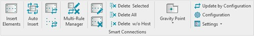
Here’s what the old toolbar looked like…
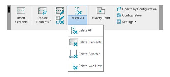
…and the new:
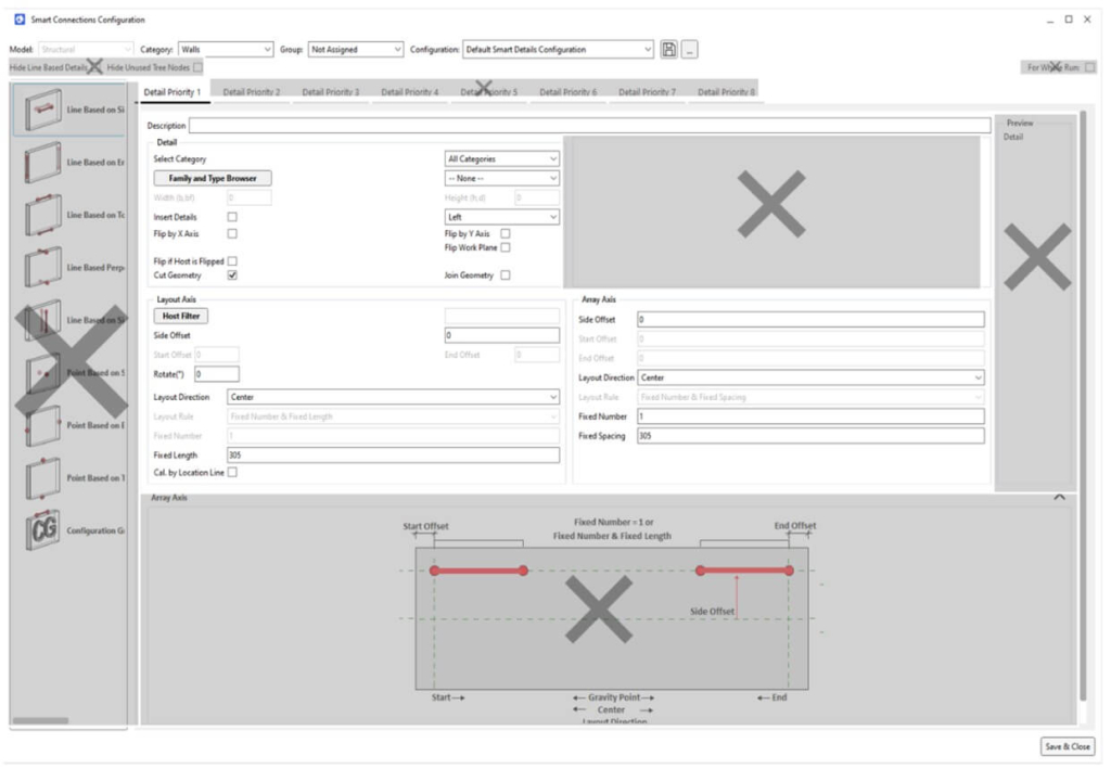
The workflow for setting up configurations has been streamlined by eliminating the Line- and Point-based family selection list (crossed out in the image below), resulting in fewer steps to achieve the desired outcome.
Users can now personalize rule priorities by specifying names and determining quantities. This heightened level of control empowers users to precisely tailor rule settings to their specific needs, thereby enhancing the flexibility and personalization of the system.
When rules are copied, the duplicated rules automatically inherit configurations from previously created rules. This feature ensures consistency and efficiency by seamlessly transferring established settings, thereby minimizing the need for redundant manual adjustments.
The new configuration window is smaller and can now be a floating window. This adjustment allows for easy parameter modifications and immediate observation of changes without closing the window. The inclusion of an ‘Apply’ button facilitates the simpler trial-and-error process.
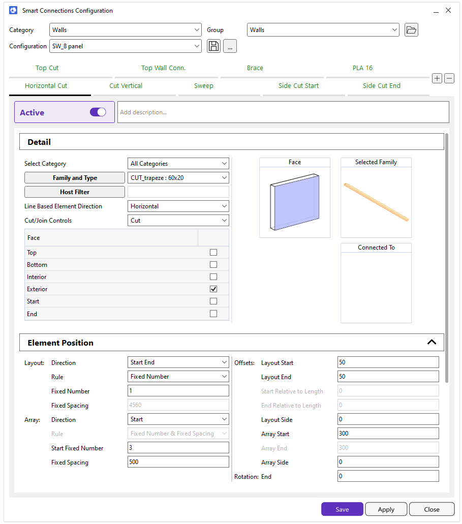
Configurations are clearly defined and categorized under expand and subtract headings. The improved layout groups relevant commands together, enhancing navigation and facilitating the selection of necessary features.
With the updated UI, the process begins by selecting the desired family, followed by additional options based on whether the chosen family is line- or point-based. For point-based families, users choose the placement position on the desired face, aided by a visual representation of the selected faces.
Following the element’s positioning under the ‘Element Position’ header, the layout, which includes the same Layout Array axes as before, remains consistent. While this section remains unchanged in content, the layout has been refined to enhance navigational convenience.
Improved searching rules
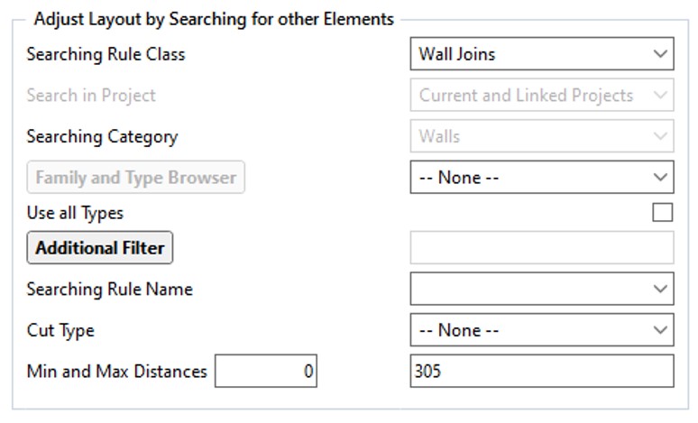
Determination of searching rules is under the ‘Adjust Layout by Searching for Other Elements’ header, which is now collapsible.
Previous ‘Searching’ window:
New ‘Searching’ window:
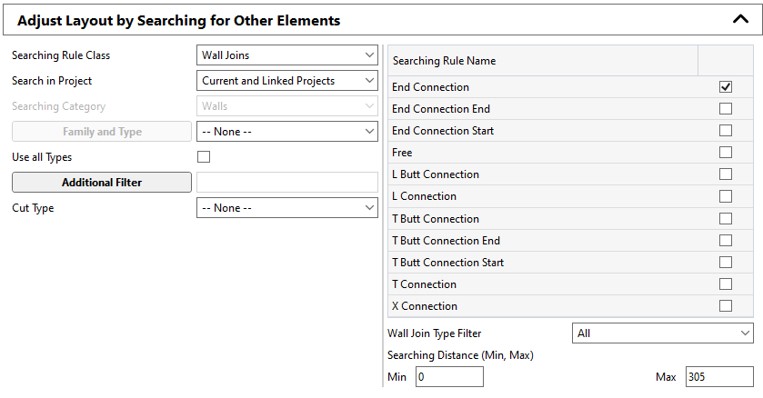
Like the previous structure, rules and their parameters are configured here to determine their functionality. Notably, rule selection has been optimized. For instance, if the intention is to apply the same rule to various Wall joins, one can efficiently set multiple wall join types by activating corresponding checkboxes in the list and selecting the desired wall connections from the selection list. The identical functionality also extends to Structural Framing and other categories.
Placement control
Within the Placement Control section, you will find abilities that operate on a toggle principle, such as flipping the family with different settings and defining how Smart Connections will assess the host.
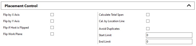
The new feature, Start Limit and End Limit, allows for setting limits on the beginning and end of a particular action or process.
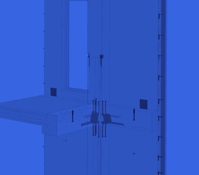
For example, when attaching nails to plates positioned above studs, especially when a stud is located near the plate’s edge, the software automatically positions the nailing 5mm from the edge. This proximity, however, is considered too close. We can establish a longer distance from the edge, such as 40mm, to address this, using start/end limits. If a connection is placed within 5mm of the plate’s edge, the software will shift it by 35mm to achieve a 40mm distance from the edge. On the other hand, if a connection is already beyond the 40mm limit, no adjustment will be made.
Floating configuration window
The configuration window now enables users to modify configurations without requiring closure. To see how Smart Connections will position the selected family based on the configured settings, simply click the ‘Apply’ button. This enhancement greatly streamlines the trial-and-error process, enabling users to quickly grasp the nuances of layout and array settings. It is now much more convenient and efficient to understand how Smart Connections settings position families based on offset values, search rules, and flip controls and prevent duplicate families from being placed in the same location.
Furthermore, the streamlined process allows for easily modifying diverse element layouts for distinct host elements. This flexibility ensures a more efficient workflow, empowering users to tailor configurations precisely to their requirements without repetitive window closures.
Free trial
Try out Smart Connections, and experience for yourself how much it can speed up detail modeling in Revit!
Current users, be sure to download this software update via your ARKANCE Dock in Revit.