We are thrilled to announce an exciting upgrade to our Be.Smart SIP Panels add-on for Autodesk® Revit®. Not only does it now boast a more user-friendly interface, but it also comes complete with sample families and configurations tailored especially for designing buildings consisting of structural insulated panels.
But the best part? You can now try out our innovative SIP Panels solution for free!
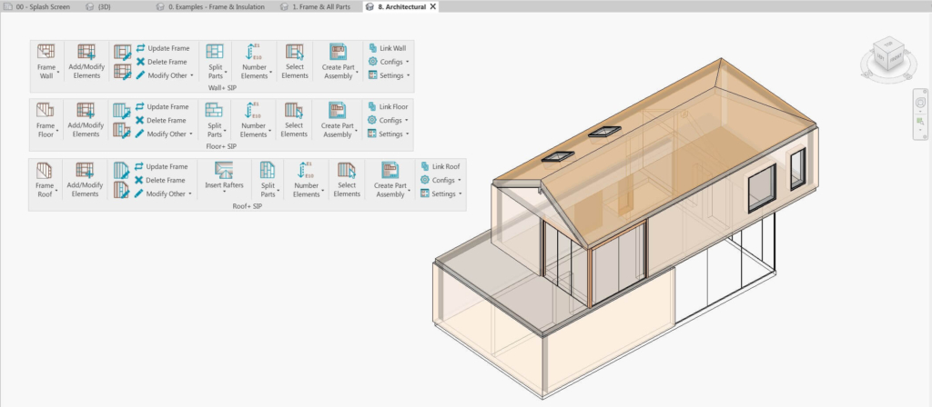
In this post, I will walk through the basic workflow so that you can follow it when trying out the software for yourself. I’ll be referring to the features found in these four ribbons.
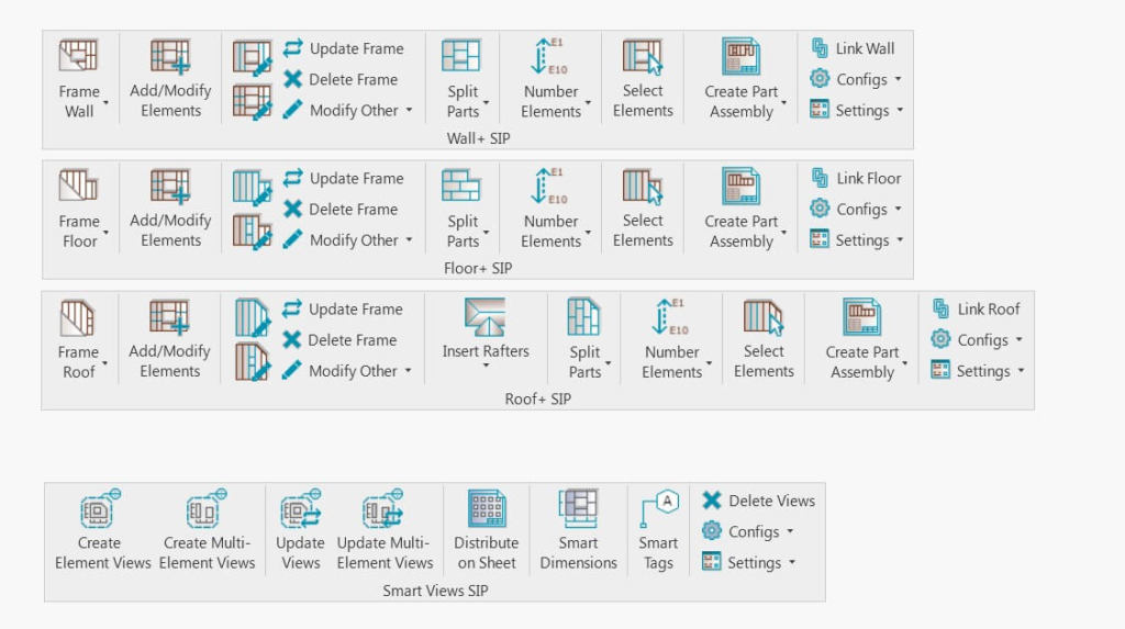
| Ribbon | Functionality needed for: |
| Wall+ SIP | modeling and documenting SIP walls |
| Floor+ SIP | modeling and documenting SIP floors |
| Roof+ SIP | modeling and documenting SIP roofs |
| Smart Views SIP | creating Revit views for SIP walls, floors, and roofs with automated dimensions and tags |
Please note that these instructions are meant to simplify testing of our SIP Panels solution, so I have used our sample configurations and families throughout. Just keep in mind that all the sample rules can be modified to your own needs and standards. That goes for all configurations: Framing, Insulation & Paneling, Numbering, Shop Drawings, etc.
Without further ado, here’s how to start creating a SIP panel home or building in Revit from scratch.
SETUP
After starting a new Revit project, make sure you save it.

Most examples shown will use Wall+ SIP, but the logic is the same for the Floor+ SIP and Roof+ SIP tools.
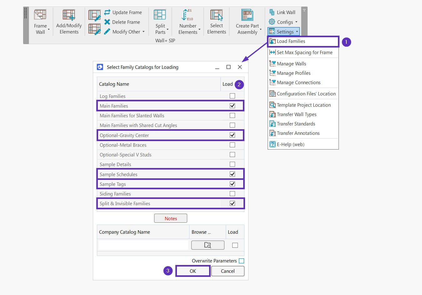
STEP 1: Load families
Choose the sample families to be loaded into the current project. SIP Panels software provides sample Metric and Imperial families for creating frames with SIP panels, tag families, and sample schedules.
Have in mind that all these sample families can be modified to your needs and standards.
For walls, we recommend loading at least these catalogs:
- Main Families
- Optional-Gravity Center
- Sample Schedules
- Sample Tags
- Split & Invisible Families
And for floors and roofs, these catalogs:
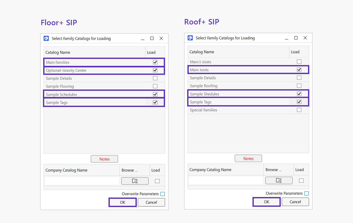
Other catalogs – Siding, Flooring, Main I-Joist, Roofing, etc. – are optional. So, you can choose to load them based on your needs.
Note! Do NOT use any other Structural Framing families! You can use other families only in special situations, in which case contact us.
After loading, you can find the families by going to Project Browser → Families under Structural Framing, Annotation Symbols, and Generic Models categories.
STEP 2: Transfer standards (optional)
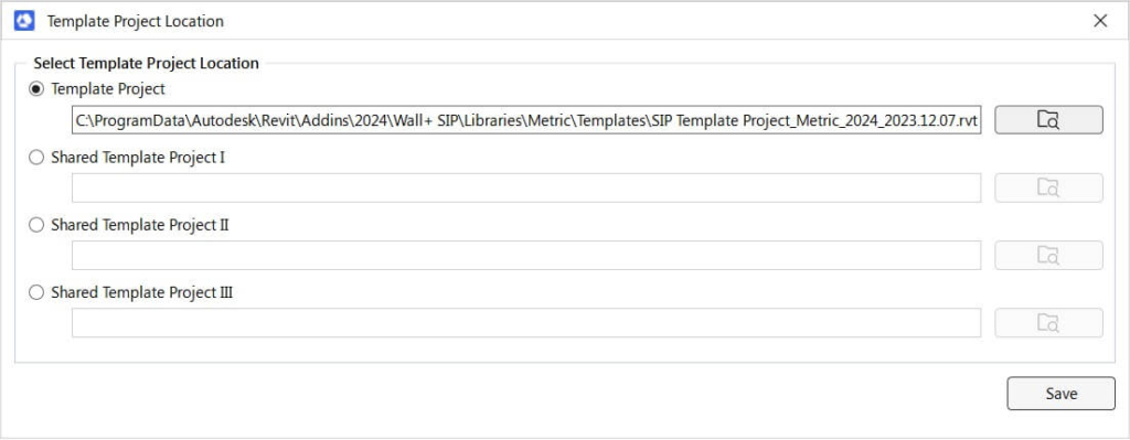
Template Project is a Revit file with sample wall, floor, and roof types, standards, and annotations. The Template Project feature allows you to transfer all needed information from a template project, eliminating the need to create Wall/Floor/Roof types and other needed elements or standards in every new project from scratch.
Before you start working with the software, we recommend using at least the Transfer Standards feature.
1. Template Project Location – the path to your template project. SIP Panels comes with a sample template project, which is mapped here automatically.
When starting out, we highly recommend using the included sample template project. Later on, of course, you can create and use your own. In this template project, we’ve prepared View Templates with Filters useful for working with SIP Panels. It does not include any Wall, Floor, or Roof types.
2. Transfer Standards – opens Revit’s Transfer Project Standards dialog window. You then need to manually select various styles, types, and settings which need to be transferred from the template project file to the current project.
At least these 6 options must be selected:
Text Types
View Reference Types
View Templates
Viewport Types
Dimension Styles
Filters
You can select more options if needed.
You can also use your own project as a template. It can include standard Wall, Floor, and Roof types and annotations that can be transferred automatically to your current project.
MODELING
Once you have already done the first two steps…
- Loaded needed sample families
- Transferred all types and standards to new/current project
…then you can start creating the architectural model that will be framed automatically later.
STEP 3: Creating basic Revit walls, floors, and roofs
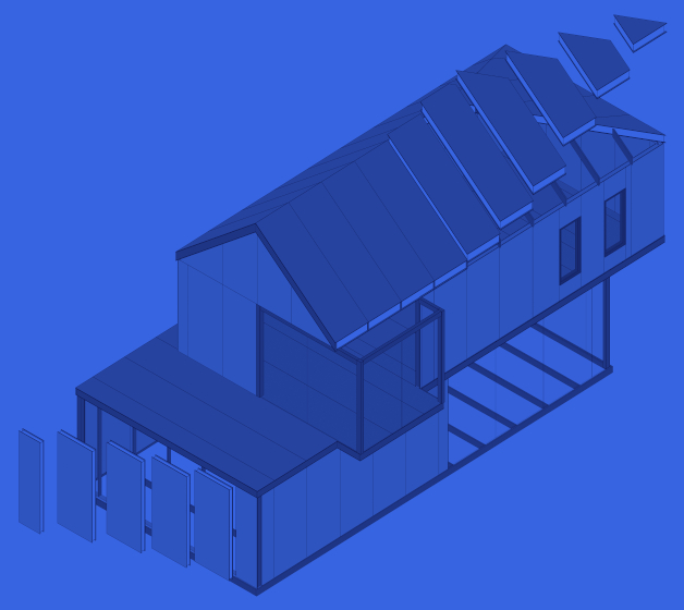
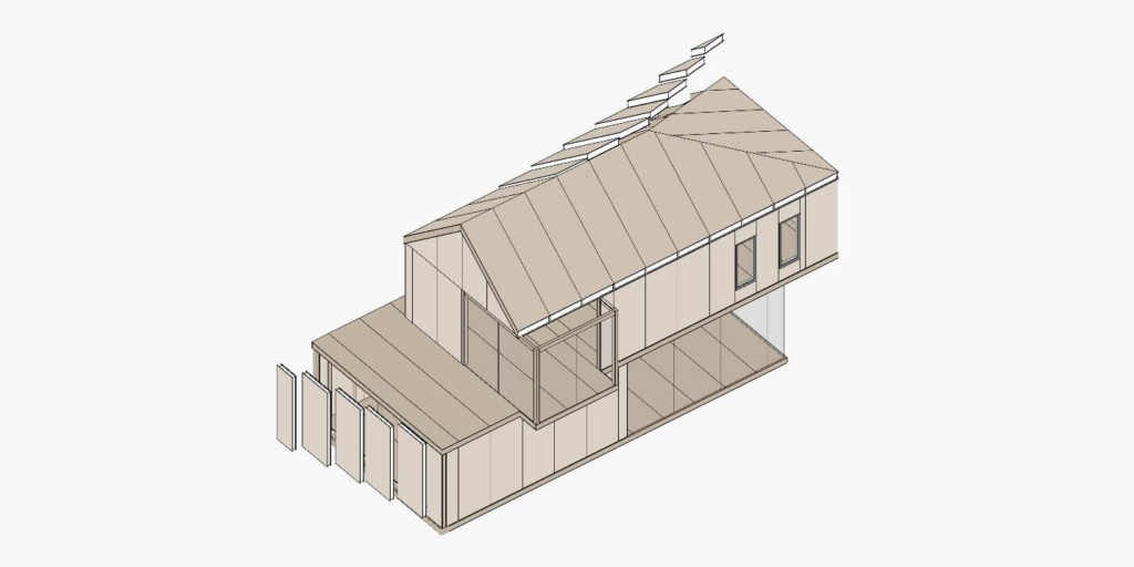
In this example, I modeled a few walls, floors, and a roof:
Modeling Recommendations
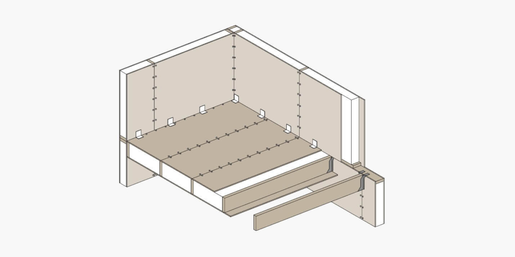
1. The wall, floor, or roof structure should be layered the way the parts of the framing will be modeled. For example:
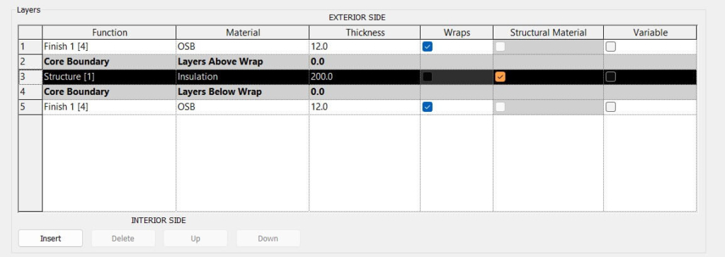
We recommend having only one Structure [1] layer inside the core boundaries for the frame/insulation layer. Add paneling layers (e.g., OSB) outside the core boundary, making sure the thickness of each layer is correct. Assign a material to each layer, ensuring it has a density parameter value so that the element’s mass will be calculated. While there is no limit on the number of layers, you need at least three layers – exterior paneling, framing/insulation, interior paneling – to create SIP panels. You may add additional layers outside of those, like nailers, siding, etc.
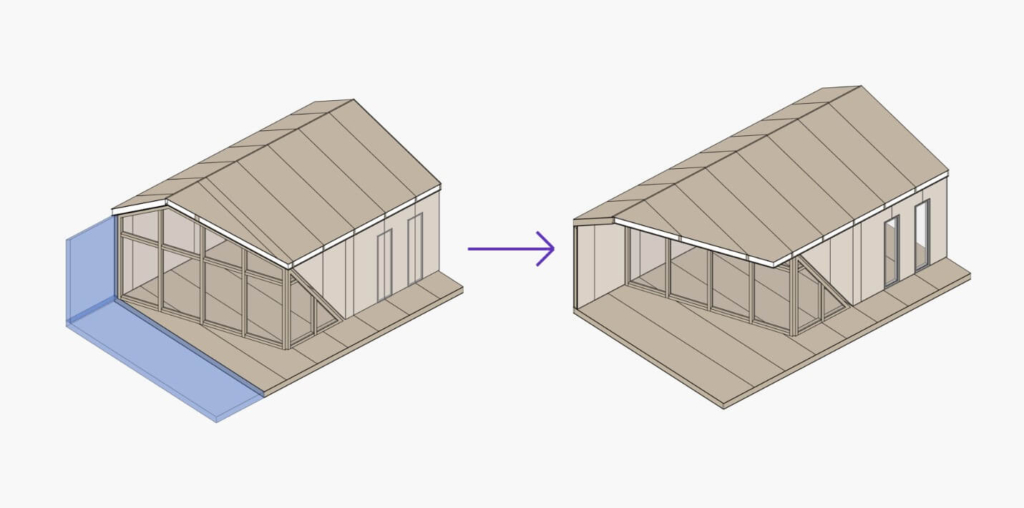
2. Avoid abnormal wall forms. Sometimes these occur when a wall is attached to a roof:
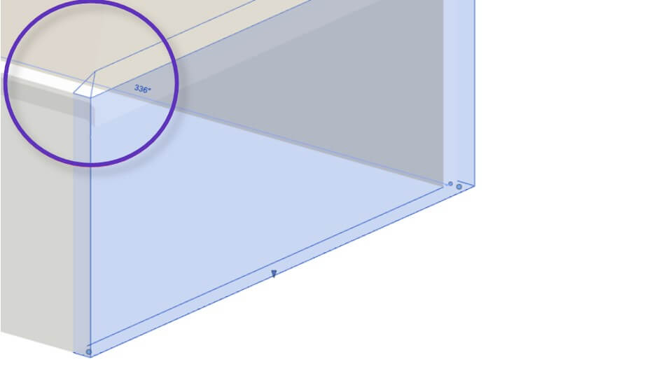
You can check wall/floor/roof shapes by isolating them in the view.
3. Walls/Floors/Roofs should be modeled the way they are to be paneled and prefabricated.
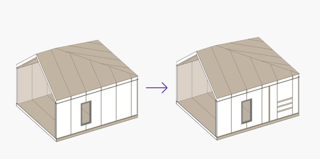
For example, if your wall SIP should start from Level 1 and end on Level 2, you should model your walls accordingly:
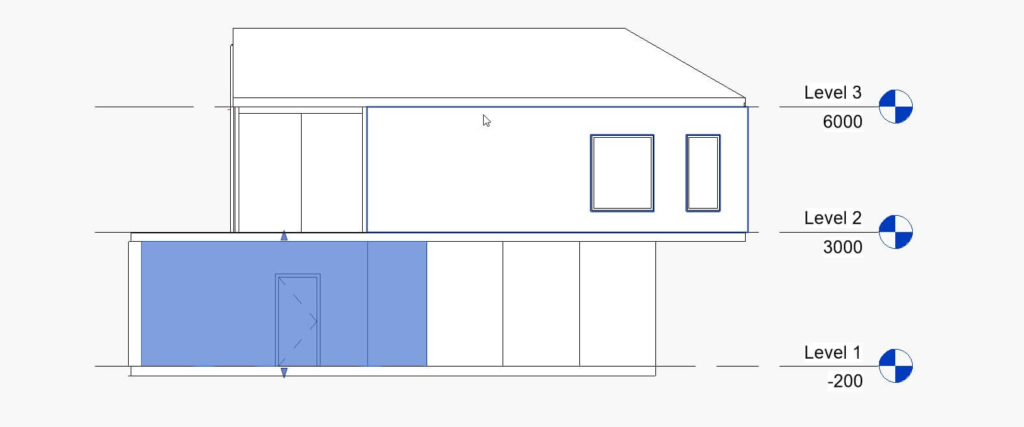
You can split walls not only manually using Revit’s Split Element command but also automatically using the included Smart Walls module. Similarly, floors and roofs can be split automatically using Floor Panel Layout and Roof Panel Layout, respectively.
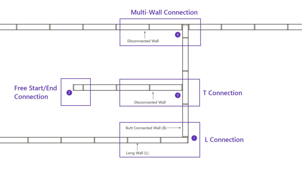
4. Pay attention to wall connections. Enumerated below are the 4 most common connections you’ll need.
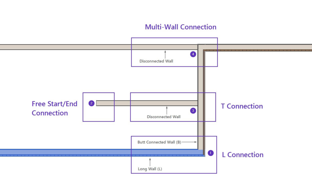
1. L Connection
For L Connections, it’s important which wall is longer and which is shorter. Make sure they connect like they should be framed/paneled. In the example image above, you can see that the selected wall is longer.
2. Free Start / End Connection
Free Start/End Connections are not connected to other walls.
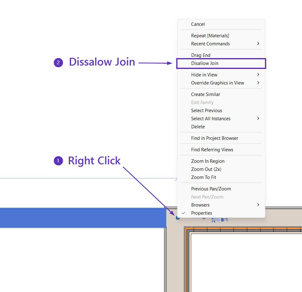
3. T Connection
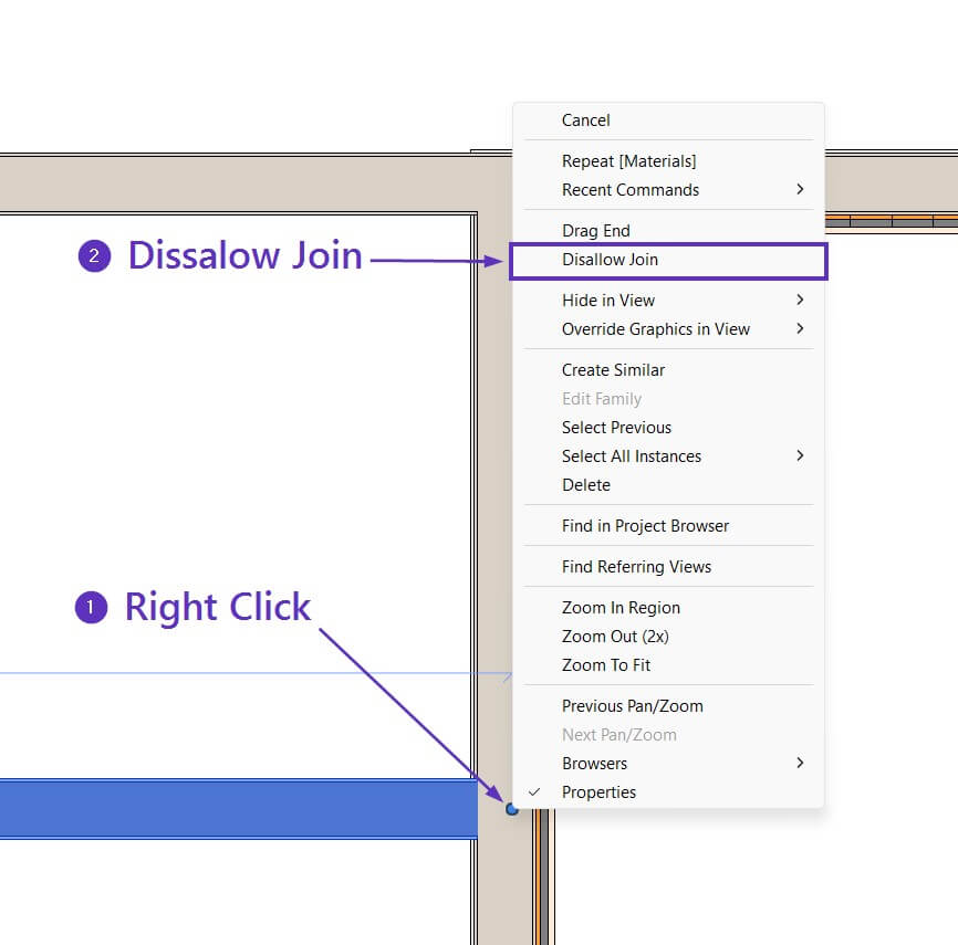
T Connections are created by intersecting walls. When creating SIP panel structures, we recommend disconnecting the connected wall (see image below) in order to get an appropriate connection for the panels. After disconnecting, you should align the disconnected wall’s end where the future frame should end.
4. Multi-Wall Connection
When multiple walls connect, we recommend disconnecting one of the walls (see image below) so that there would be only two walls connecting. In this example, I disconnected an interior wall, so two exterior walls will be framed as an L Connection. After disconnecting, be sure to align the disconnected wall’s end where the future frame should end.
This is what the result will look like after creating the SIPs:
After the model is created, you can start using the sample configurations to create the frames.
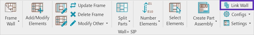
STEP 4: Link wall / floor / roof
Three layers are required to create structural insulated panels:
Paneling (OSB)
Frame with Insulation
Paneling (OSB)
You may add additional layers as well, like nailers, sidings, etc. In this example, we will focus on the most important settings for the three required SIP panel layers.
This example is for a wall, but the logic is similar for floors and roofs.

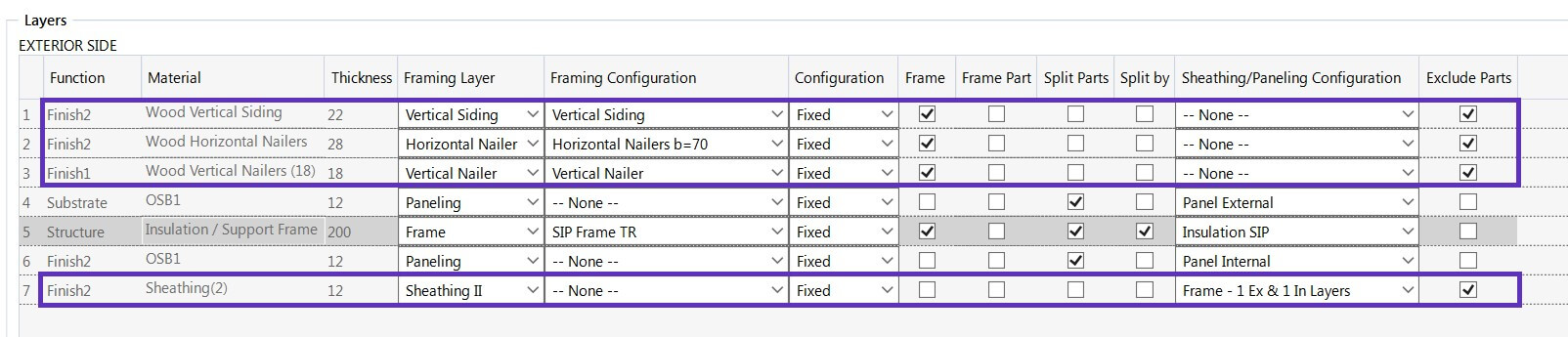
Here are brief explanations of the numbered sections:
- This is where you select a wall, floor, or roof type.
- Framing Layer – Select Frame for the Frame/Insulation layer and Paneling for the internal and external paneling layers.
- Framing Configuration – Select a framing configuration with the definition of all framing parameters. A sample configuration, SIP Frame that comes with our SIP Panels solution, was used here, but you can also create your own later on. In this example, we’ll split the internal and external panels by the main Frame, so None is chosen for the internal and external paneling layers.
- Frame – Choose whether layers should be framed during the framing process. In this example, we’ll frame only the main Frame/Insulation layer.
- Split Parts – This option should be selected for all three SIP panel layers, as Insulation and Paneling are created as Parts category in Revit.
- Split by – This option should be selected for the main Frame layer, as we’ll split the Insulation and Paneling layers by the Structural Framing elements that are defined in the SIP Frame sample framing configuration.
- Paneling Configuration – Select a paneling configuration with the definition of how SIP panel layers should be split. Sample configurations that come with our SIP Panels software are used here, but you can create your own later on.
- Exclude Parts – Select the parts that need to be excluded from the wall/floor/roof. SIP panels are created as parts, so this tick mark should be OFF for all three layers.
For more complex situations, you can frame paneling layers using invisible elements and split internal and external paneling layers with those elements instead of the main frames. Such an example can be found in the SIP sample project:
Watch this video to see the workflow starting from STEP 5:
STEP 5: Create frame, split parts
Before framing, create sheathing or paneling using Revit Parts.
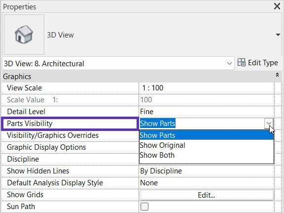
In order to see the sheathing or paneling, you have to select Show Parts or Show Both in View Properties → Parts Visibility.
And if you transferred View Templates and Filters from the sample Template Project in Step 2, you can use these View Templates with Part visibility turned ON:
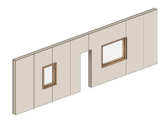
Main frame with parts
Only the main frame and all part layers (internal/external paneling, insulation) will be visible
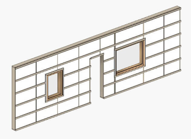
Frame with insulation
All framing layers and insulation will be visible (internal/external paneling is not visible)
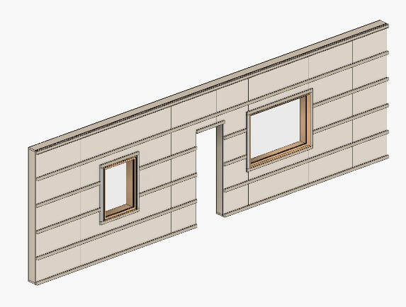
Frame with parts
All framing layersand all part layers (internal/external paneling, insulation) will be visible
Of course, you can also create your own view templates with various filters.
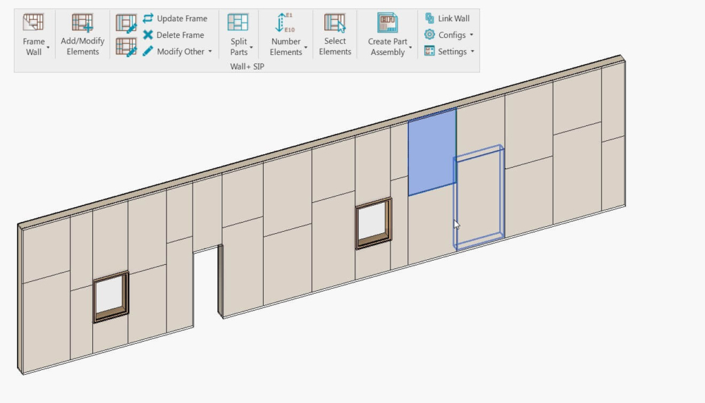
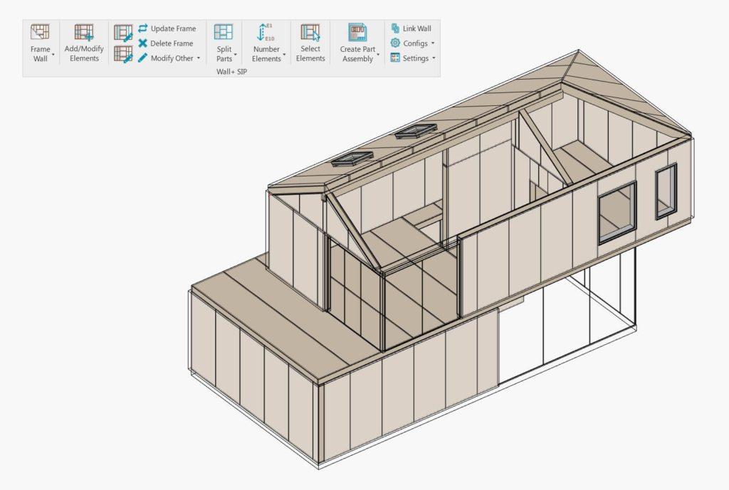
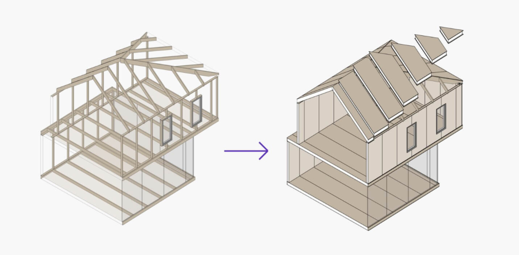
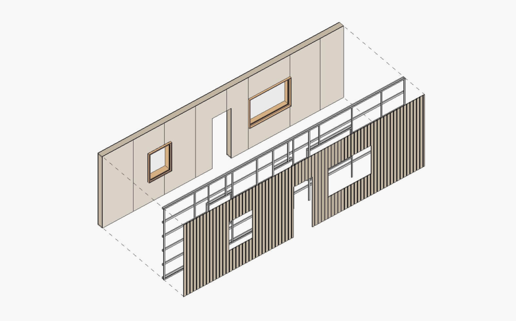
Now, you can select all of the walls (or floors and roofs, as the case may be) you wish to frame and use Frame Wall. In this example, selected wall, floor, and roof frames by chosen sample configurations were generated, and parts for insulation and paneling layers were split at the same time:
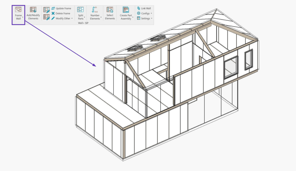
In the image above, you can see the main frame with insulation. And here, you can see the internal and external paneling layers as well:
Please note that these sample configurations can be modified to your needs and standards. That goes for all configurations: Framing, Connections, Numbering, Shop Drawing, etc.
In this example, all Insulation and Paneling parts are split by the main Frame together with the Frame Wall (or Frame Floor/Roof commands) because the Split Parts with “Frame Wall” Command is turned ON in the sample configurations:
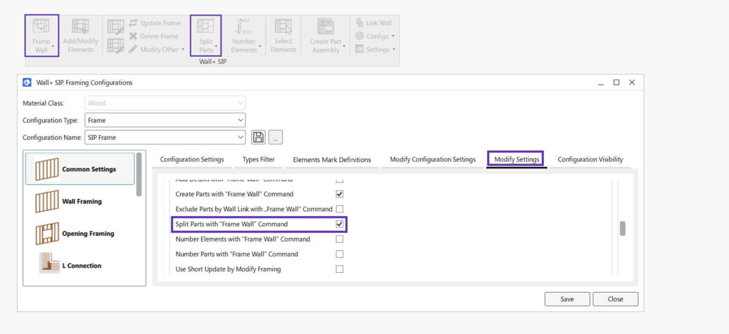
If this tick mark would be unticked, you’d have to use the Frame Wall command and then use the Split Parts command after that.
STEP 6: Modify/Update (as needed)
The software is very flexible when it comes to modifying the frames after they’ve been generated by the settings in your configurations. You can modify the frames using features from the Add/Modify Elements, Edit Elements window and using Modify Frame if you need to. There are many possible ways and workflows, so the following are just a few examples.
- Vertical and horizontal additional elements were added automatically:
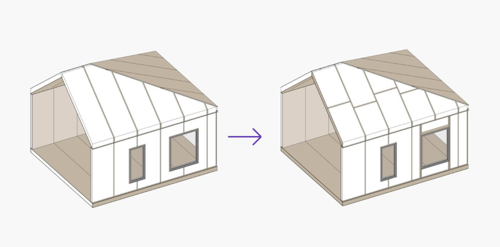
- Frames with SIP panels were updated based on the changes made in the architectural model (the wall and floor were enlarged and an opening was added):
- The instance of the Roof framing configuration was modified to have horizontal bridging elements with alternating offsets. And instead of distributing the posts from the start of the wall, we changed it to have the spacing in the middle of the wall:
STEP 7: Insert connections (optional)
When you have all walls, floors, and roofs framed and panelized, you can move on to creating connections. Using features from the Smart Connections ribbon, you can insert hundreds of elements into your project with just a few clicks. Time-saving features ensure fast, accurate modeling of highly detailed projects. You can easily follow project changes and quickly modify and update fasteners and joints as needed.
STEP 8: Finish layers (optional)
You can frame additional layers, like secondary frames, nailers, siding, roofing, etc. For example, in Wall Link, I created additional layers for nailers, siding, etc., as seen here:
The additional layers are created using the Add Additional Layers command. Result:
DOCUMENTATION
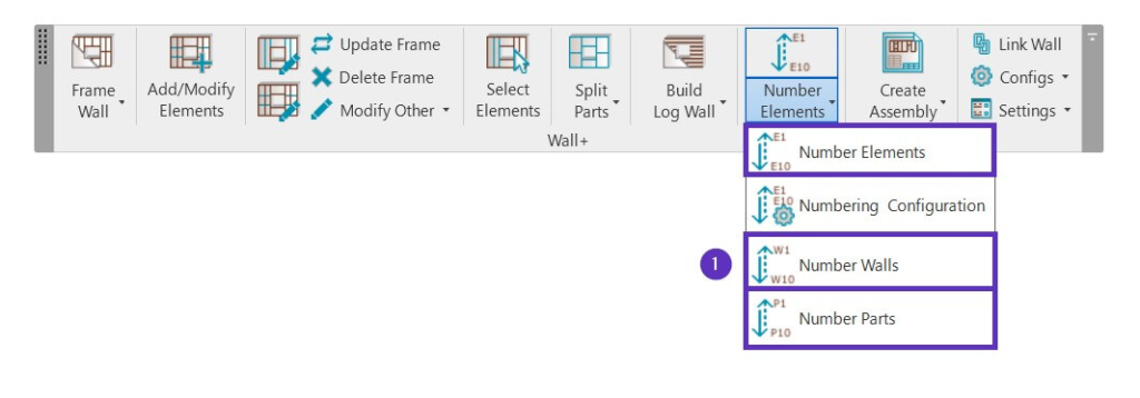
STEP 9: Number elements
Before creating shop drawings and schedules, you need to make sure that all elements are numbered. First, to number the hosts, use the Number Walls (Number Floors/Roofs), Number Parts, and Number Elements commands. All elements will have all necessary information not only about themselves (for example, FM Sort Mark) but also about their hosts (Walls/Floors/Roofs).
Please note that the sample Numbering configurations can be modified to your needs and standards.
STEP 10: Create assembly drawings and schedules
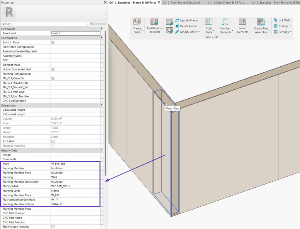
When all elements in your project are numbered, it’s time to create shop drawings and schedules and place them on sheets. All you have to do is select single or multiple parts and use the Create Part Assembly feature, which is for creating assembly views and schedules for SIP Panels.
Parts can be selected manually or automatically. In this example, I selected all Main Parts by Layer in Level automatically and then used Create Part Assembly:
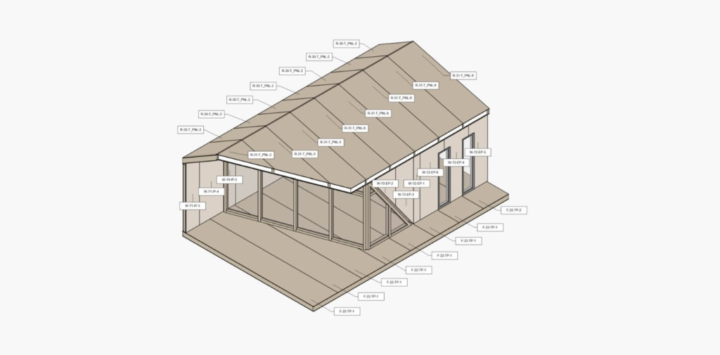
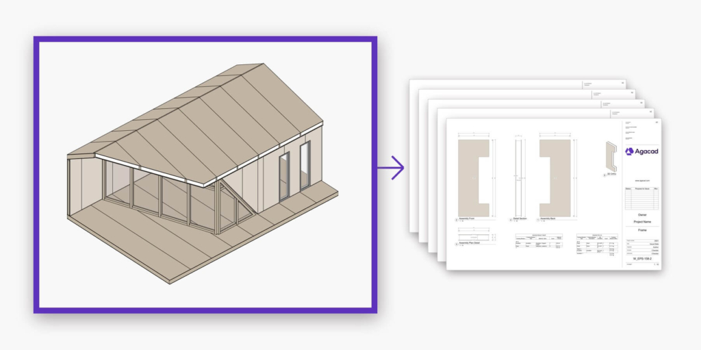
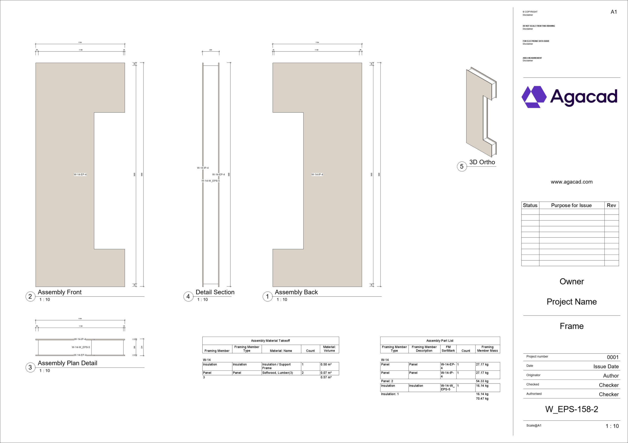
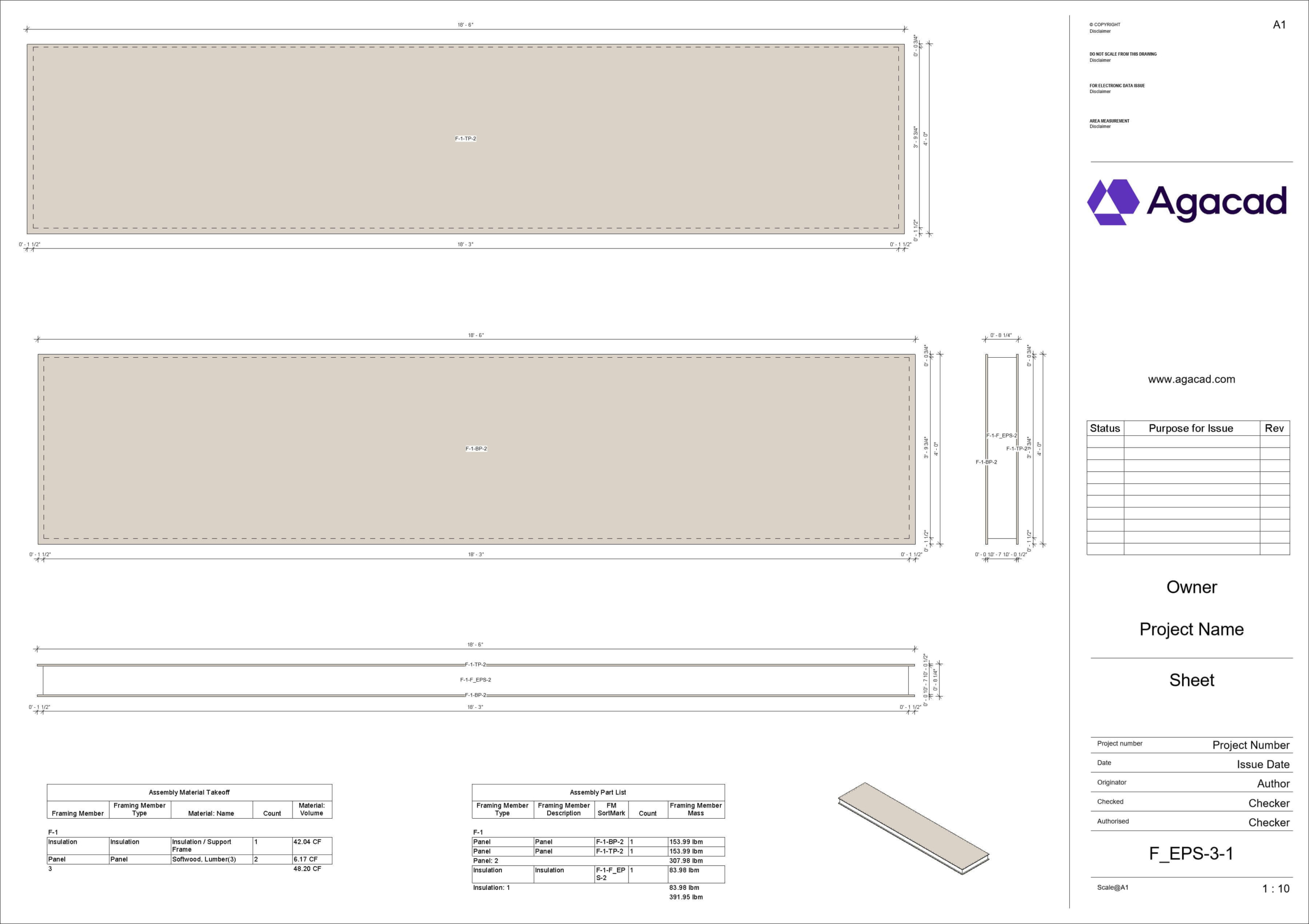
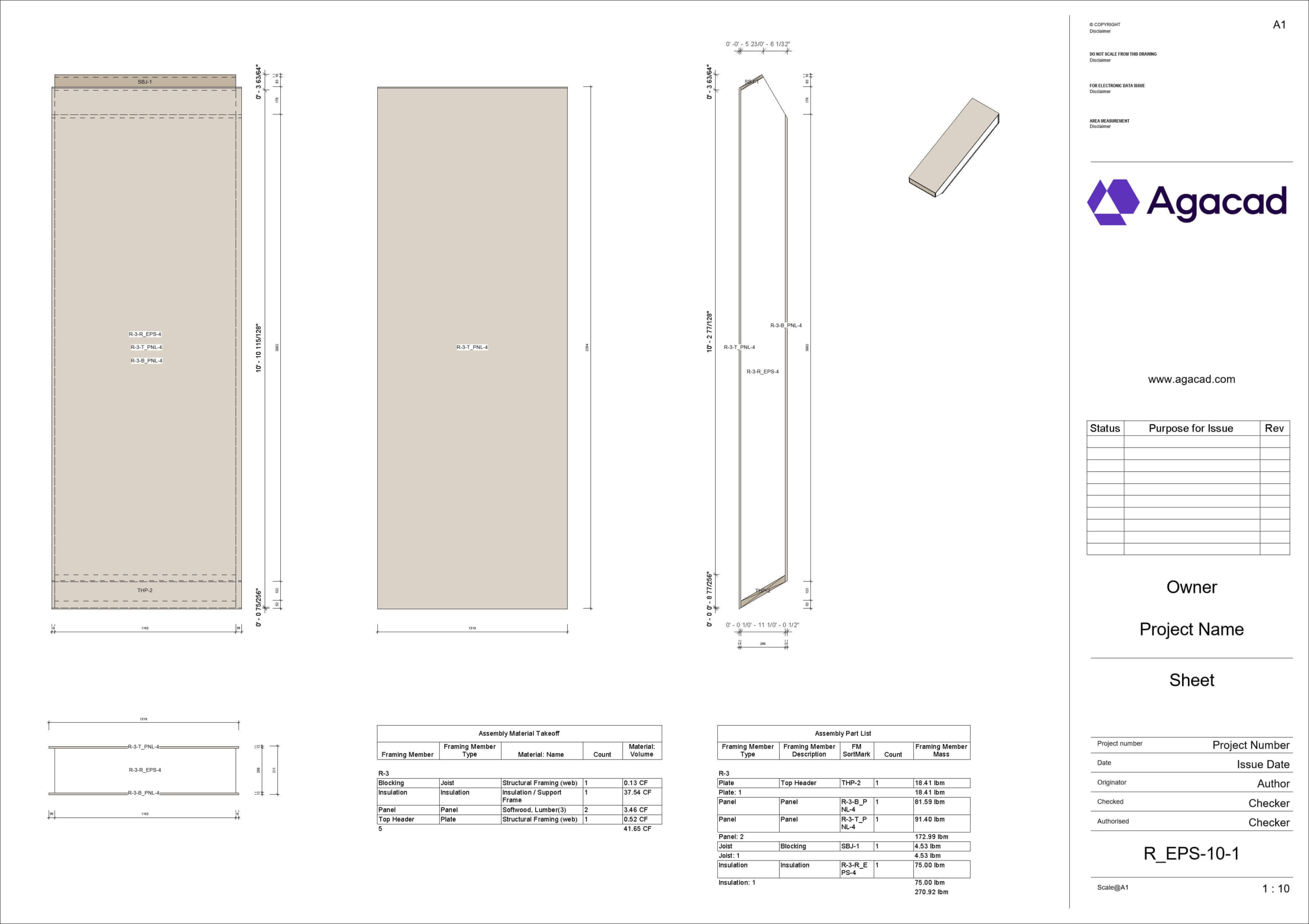
As a result, wall SIP assembly schedules and drawings with tags and dimensions are generated automatically:
These are examples of floor and roof SIP panels:
STEP 11: Create Revit views
Creating assemblies is a useful feature because it lets you take advantage of the benefits that working with assemblies brings, such as separate drawings for assemblies and easier project documentation. But what happens when you need to detail individual elements that are already part of an assembly?
That’s where features in the Smart Views SIP ribbon come to the rescue.
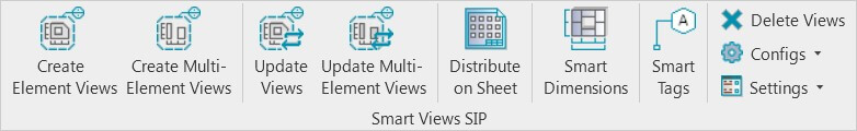
The Create Views and Create Views for Multiple Elements features are suited for Revit users who need to make drawings of sections and elevations of any building element, all the way from preliminary design stages through to a detailed design. It could be for a wood-framed wall or window, an elevation of selected walls/floors/roofs, or a section of a particular connection, etc.
It’s especially useful for SIP walls/floors/roofs because in Revit it’s impossible to create an assembly of elements that are already assembled (like SIP panels). So, you can create assemblies for SIP panels and then use Smart Views SIP to create auto-dimensioned and tagged views for elevations or walls/floors/roof containing all SIP panels.
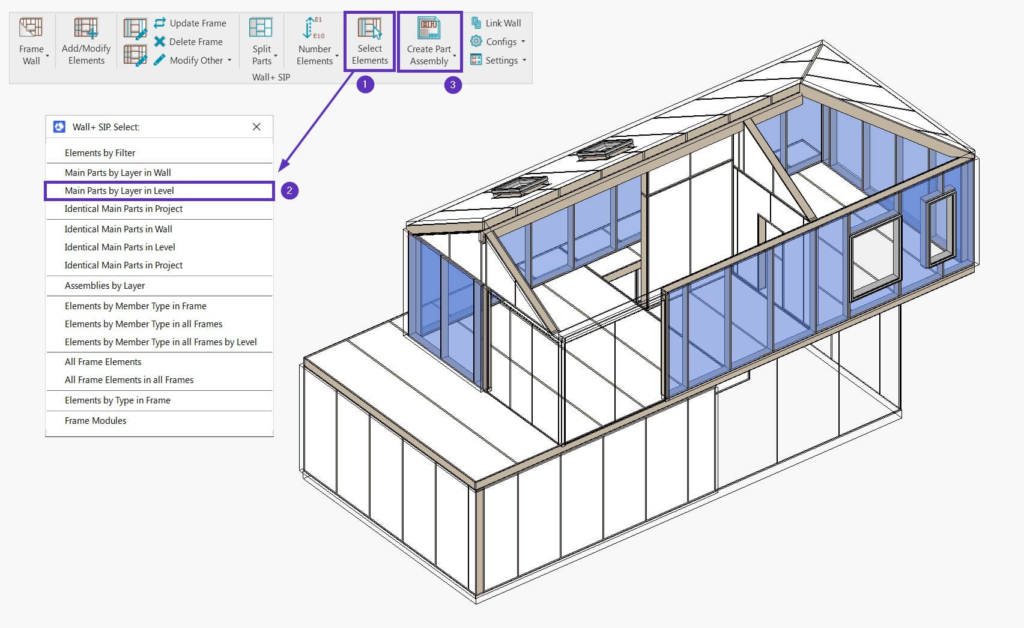
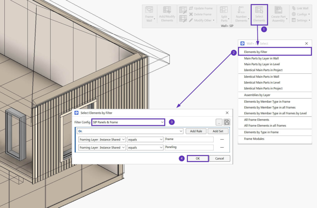
In this example, we’ll select all elements from the main frame layer (studs, plates) as well as insulation and OSB parts. This can be done automatically by using Select Elements → Select Elements by Filter and choosing one of the sample selection filter configurations:
When all needed elements have been selected automatically, use the Create Views for Multiple Elements feature and select a sample configuration for creating views:
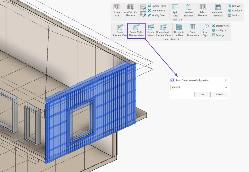
As a result, Revit Detail Views with dimensions and tags are generated automatically, where you can see all SIP panel assemblies in the whole wall:
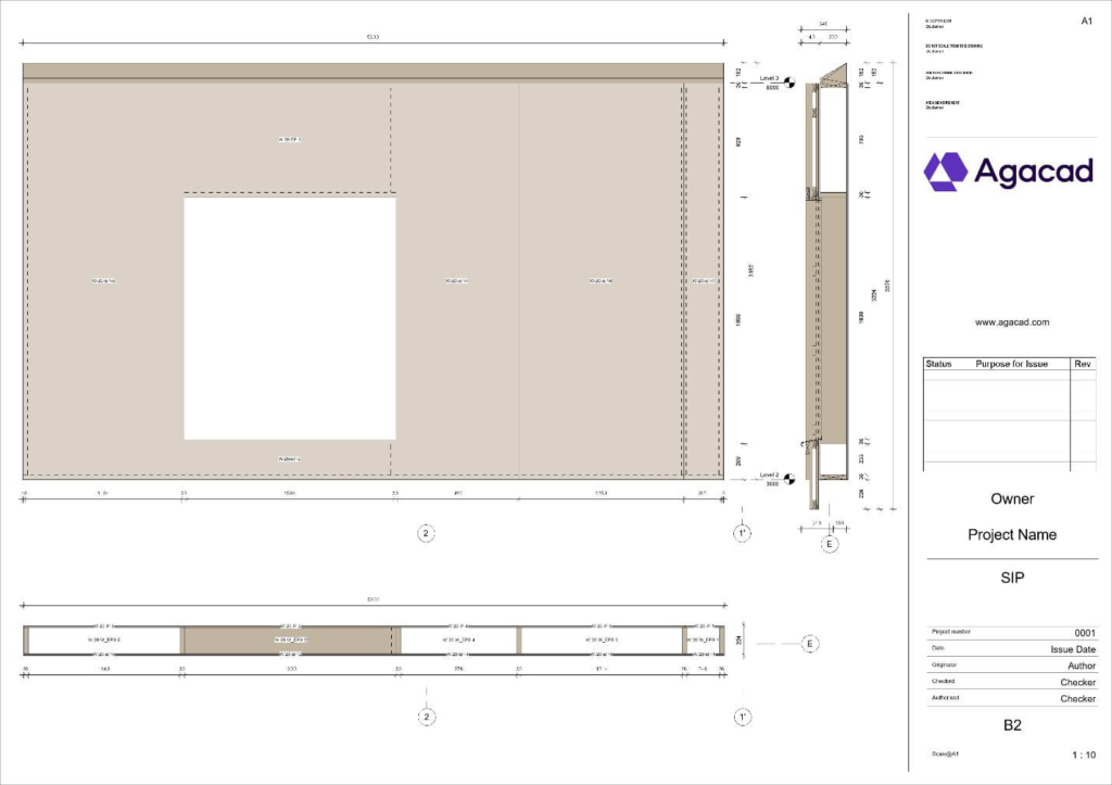
These views can also be distributed automatically using Distribute Views on Sheet.
That’s it!
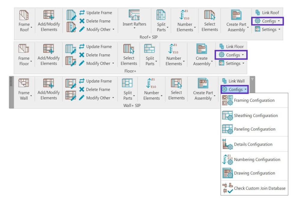
All sample configurations used in this explanation can be found and modified under Configs for roofs, floors, and walls, respectively:
Free trial
Download a free trial of SIP Panels, and test the software for yourself! Let us know if you’d like to have a personal demonstration online or if you have any questions.