Designers have tried to make CNC machines work with Revit for a long time. There’s often a demand for specialized tools or software that can make things happen easier, and it is possible using solutions that can export BTL, WUP, BVX and other files from Revit.
There’s no need to take the tougher road using other file formats such as DWG and DXF that require ABViewer for G-Code generation. We have a few efficient solutions in place — Agacad’s CNC Exporters for exporting data of timber or light steel wall, floor, and roof frames from Revit into a format readable by CNC machines. Although there are a number of Wood / Metal Framing CNC Exporters, here I will briefly review only one of them in more detail.
WEINMANN BTL and BTLx exporters
This tool offered by Agacad facilitates direct export of wooden wall floors, roof frames, and trusses from Revit to WEINMANN or other CNC machines that can read the BTL format. The exported file contains all the information needed for cutting. And for timber house manufacturers, it is now possible for you to predefine rules and operations for automated CNC machines such as marking, drilling, sawing, trimming, etc., directly from Revit.
“Why WEINMANN?”, you may ask. Well, that’s because it has one of the most perfectly coordinated wood framing processing production lines around. It is a leading machinery and equipment manufacturer for timber houses, and its offerings are being used worldwide.
Both BTL and BTLx are standard formats for timber fabrication like beam processing, which is quite detail-oriented and complex. While the BTL extension witnesses worldwide usage, the BTLx format is newer and can describe parts in geometry that are independent from the machine. That said, the exporter tool is compatible with Autodesk Revit 2019-2021 at the time of writing this article.
Learn the Process
The biggest mistake many designers make is not trying to understand the CNC workflow — the general fabrication process, modeling best practices, the limitations of the procedures, element isolation for export, and the CAM software.
As for the application, you’ll have to use Agacad’s Wood Framing software to create framing elements. It ensures that the geometry and other data from the Revit project are exported along with the file. As for looking at the file, you can use the BTL viewer. Through the exporter tool, you can now have BTL and BTLx extensions readable by automated WEINMANN CNC machines.
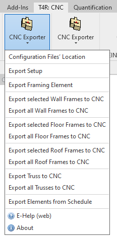
Simply click on the CNC Exporter icon after installing it, and select any of the trusses, roof frames, or walls to be exported from a Revit model to a WEINMANN BTL or BTLx file with a single click. As simple as that.
All the operations can be viewed in detail in the BTL viewer for every member of the frame at hand. It can even handle processing definitions like texting, cutting, longitudinal cutting, drilling, marking, and pocketing, among others.
You can also configure the setup to automate element identification and marking of columns, joists, rim joists, studs, girders, and plates.
It’s imperative that you understand that the devil’s in the details of the process. How you use the tools and link them together matters a great deal more than the tools themselves.
Export discrete elements
Your CNC machine is not a 3D printer. You can’t be dumping all your messy models and expect it to all work out. What you have to do is export the elements from Revit using the BTL exporter and then set up the job right there. That’s where the CNC machine comes into the picture.
Using Revit to create timber frame buildings
Consider that you need gyp wall panels that have been created from a standard Revit wall. That’s what we mean by separating the bits. Slice up the wall, get the wallboard to show, cut it and send it out for fabrication. You can use AGACAD’s Wood Framing BIM & 3D modeling software for this purpose.
In the case that you’re using Autodesk Revit without any extensions for a more effective workflow, you can send framing data to CNC machines manually.
How do you do that?
- In Revit, go to Current View Properties by default on the left panel, and change Parts Visibility to Show Parts.
- Create parts after selecting the wall. You’ll need a panel array, preferably 4×8 feet. That’s basically just line work.
- Select the wall, use the Divide Parts tool from the top menu, and then edit the lines according to your division strategy.
- That’s it. Finish your edit, and now finish your sketch.
- All your wallboard panels are cut and ready to be exported in DXF format.
Further steps
If you export 3D solids as DWG/DXF/SAT or clean 2D sections as DWG/DXFs, tool pathing henceforward becomes a no-brainer when you import those parts into your CAM software.
You can go beyond this. For all the times you’re working on a complex model, you can use Revit families as a placeholder or create a simple representation of your idea and then build upon it in the CAM software. Again, for instance, you might start with a solid in Revit and go on to export that to Blender to manipulate it further before bringing it into your CAM software.
It can get simpler too. If you have to overlap two solids in Revit, all you need to do is insert the vectors required for the tool pathing for the joint in question.
Final thoughts
When it comes to the actual craft of CNC, building things goes beyond simple design and architecture. You have to understand the tolerances and strengths of the materials, the joinery details, the weights. As you can guess, it’s really about the entire process. No single tool or piece of software can make it work, but strategies and people can.
About the Author
Peter Jacobs
Peter Jacobs is the Senior Director of Marketing at CNC Masters. He is actively involved in manufacturing processes and regularly contributes his insights for various blogs in CNC machining, 3D printing, rapid tooling, injection molding, metal casting, and manufacturing in general.