What’s the latest building style you can frame with AGACAD‘s Framing software for Autodesk® Revit®? Heavy Timber and Post-&-Beam structures! 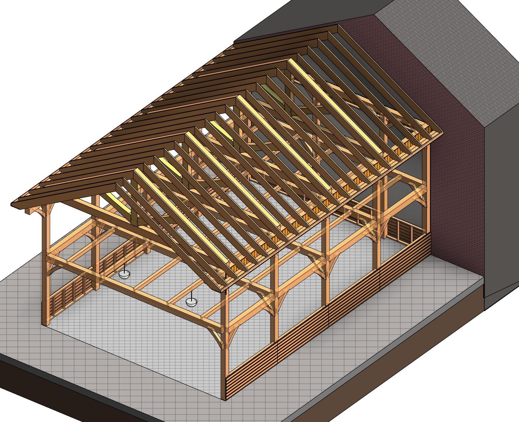 The new BIM software Wood Framing OAK is powerful and flexible in automating the design process for even the most complex and unique structures – it’s just a matter of figuring out a workflow and setting up required families.
We’ve already covered multi-layered timber frames and frames with SIP panels for walls, floors and roofs, high-quality ventilated facades, and architectural curtain walls with highly detailed elements. So, now it’s time to move on to framing with massive timbers.
Using Wood Framing OAK and sample families, you can create heavy-timber-framed walls, floors and roofs. Also, distribute and manage details used in connections with cuts common for oak frames by using our BIM solution Smart Details and, finally, prepare shop drawings, cut lists, and even export wood elements and details to any CNC machine and CAD/CAM production line, including Hundegger and Weinmann.

Framing the supporting structure and creating connections with cuts common for OAK Frames
Once Walls, Floors and Roofs have been modeled in Revit, it’s time to frame them. Wall+, Floor+ and Roof+ modules (they are included in BIM solution Wood Framing OAK) have all the features that are required to predefine your own configurations for framing. Standardization and automation of the wall, floor and roof framing process and shop drawing generation allows you to skip major hurdles in building design. These are the prominent time-saving Wall+, Floor+ and Roof+ functions.
1. Wall and Floor Framing

The framing configuration options allow you to predefine custom rules for distributing Wall posts and beams, bracing, bridging and siding, also Floor supporting structure, including battens, sheathing and flooring.

After the rules are created, walls and floors are framed in a few clicks:

Bracing is also added automatically, with the help of Wall+:

2. Connections
Everything looks OK, except that we don’t see connections with cuts common for post and beam structures, and that is where Smart Details comes into play.

Smart Details instantly adds any number of face-specific intelligent details – which adapt to changes of the host-element – throughout BIM models. Rules can be easily set up to insert or adjust details based on depth, adjacent elements, and more, this allows us to create even the most difficult connections. Also, it’s completely flexible as everything depends on the family that you are distributing automatically – you can create even the most specific ones to meet your needs.
Here are a few Wall Post and Girder connection examples created automatically using Smart Details:
Mortise and Tenon Join
 |  |
Shoulder Cut Join
 |  |
Girder to girder connections:

3.1. Roof Framing – Trusses
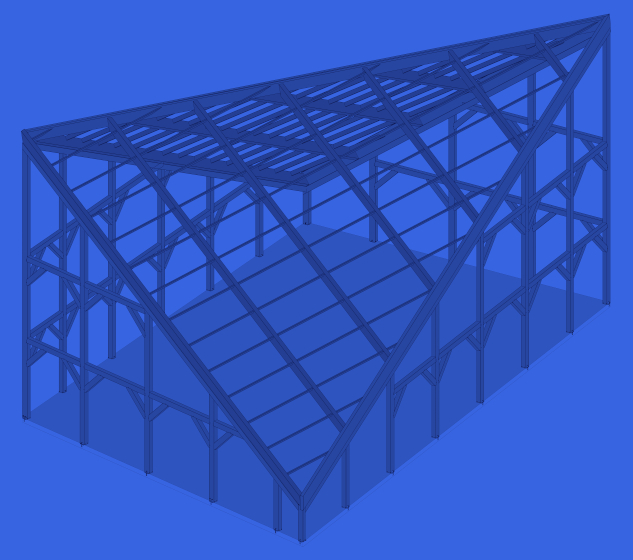
Now that we have already created the supporting structure for Walls and Floors, we can frame the Roof.
Roof trusses are created automatically with the help of Truss+.

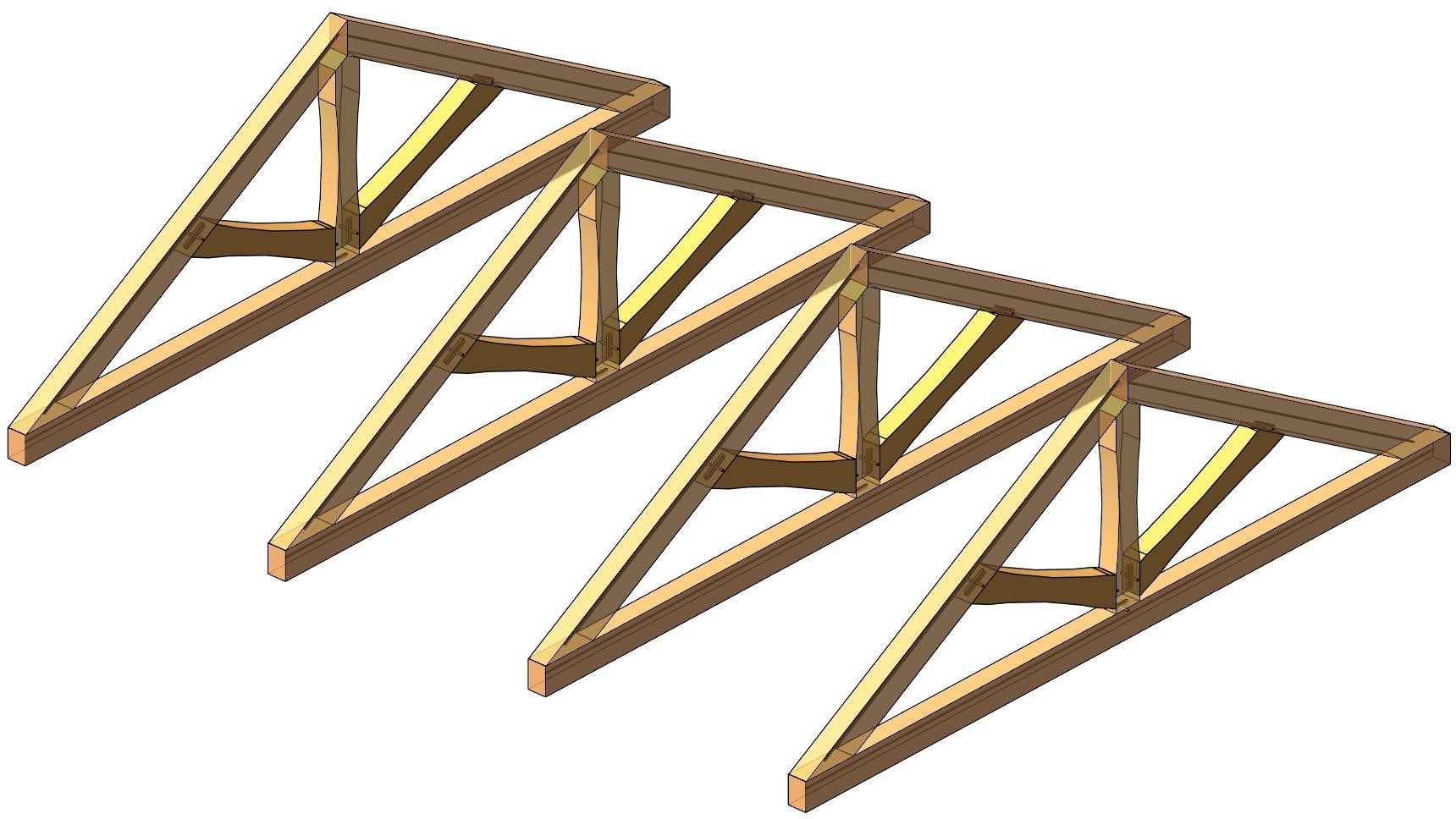
We just create one Truss, align it by chosen spacing, and that’s it!
Again, we can create connections using Smart Details:
 |  |
 |  |
With Wood Framing OAK, you can create any type of Truss, by changing Truss members and cut details:

3.2. Roof Framing – Rafters
Common rafter framing, batten, sheathing and roofing is generated using Roof+:

The framing configuration options allow you to predefine the supporting structure, how openings, edges, bridging, nogging, blockings, details should be framed, and more:

Our roof framing solutions for rafter structures tackle two major steps:
- Taking an architectural roof and turning it into panels by faces.
- Framing the panels.

You can read more about the new features for framing automated Rafters in Revit in this blog post:
NEW FEATURES for Wood/Metal Framing: Automated Rafters in Revit
So, we just split the roof by faces, frame it, align and get the result:

Final touches
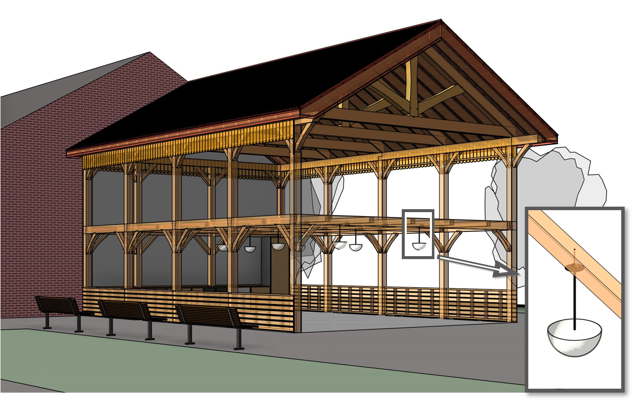
Now that we have the supporting structure, we can add other layers, like battens, roofing and siding for the walls…
 |  |
 |  |
…and even lighting fixtures can be distributed automatically, using Smart Details:
Documentation
Finally, we can create shop drawings and schedules with all elements automatically dimensioned and tagged.
Here’s an example with Roof Rafter structure:

If you need to produce drawings with all front/back/top/bottom views, sections, etc. of all individual joists, braces, girders and other members, I highly recommend using our BIM solution Smart Assemblies.
CNC Export
CNC Exporter is a separate software for Autodesk Revit users that can automatically assemble all framing members in predefined ways and export all necessary data for timber house manufacturing using CAD/CAM production line. It enables your model data to be automatically exported for manufacturing.
A few elements from the heavy timber frame were exported using AGACAD CNC Exporter:
Column
Girder
Diagonal Truss web
Hope you’ve enjoyed this overview of creating heavy mass timber structures using our BIM software Wood Framing OAK which includes all functionality of BIM solutions Wood Framing Wall+, Floor+, Roof+, as well as Smart Details!