Here is a question from MEP engineer who designs fire protection systems using Revit® MEP: We don’t layout sprinklers in architect drawing instead we link architect drawing and do layout sprinkler in our drawing. This may prevent me from picking a wall since architect drawing is linked in our drawing. How to distribute sprinklers in the linked Autodesk Revit files easily?
In that case our BIM solution Smart Sprinklers could be a good helper for any Revit MEP user. I’ll give you a short tip how to distribute sprinklers in the linked files quickly using Smart Sprinklers tools. If you work with linked architectural model, then please follow these steps:
- Select “Insert Position Symbol as Virtual Group”;
- Select Space from the plan view;
- Press Esc;
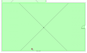
- Pick point near the wall (that will show X axis) from the link:
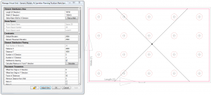
The space boundaries will be accurately scanned and you will be able to distribute air terminals in the space. All the distribution could be made using a smart distribution dialog block which allows you to define distances in between sprinklers in X and Y directions:
Using the Smart Sprinklers solution you will be able to distribute your elements according to your required elements elevation, distances between elements or a number of elements in some directions. Offset functionality is also included in this solution. You could define minimum distance to a wall or maximum elements in X and Y directions.
So Smart Sprinklers is the very useful solution for sprinkler distribution both in the linked file and Revit projects. Try it and make sure yourself!


