As always, our team is dedicated to enhancing our Wood Framing and Metal Framing BIM software, designed for creating walls, floors, and roofs in Revit for prefabricated timber and light-gauge steel-framed buildings.
Several notable improvements have been implemented, which not only increase the software’s functionality but also ensure optimized workflows and a seamless user experience so that people with different backgrounds – whether architects, engineers, designers, or students – can work with it intuitively and effortlessly.
Our latest update brings a host of new features and enhancements that make it easier to reap the full range of benefits our Wood Framing and Metal Framing plugins provide.
Simply put, we want the tools at your fingertips to help you work as efficiently and effectively as possible. So you can get your job done quickly and accurately. We are confident that our Wood Framing and Metal Framing BIM software will continue to be essential tools for professionals in the industry.
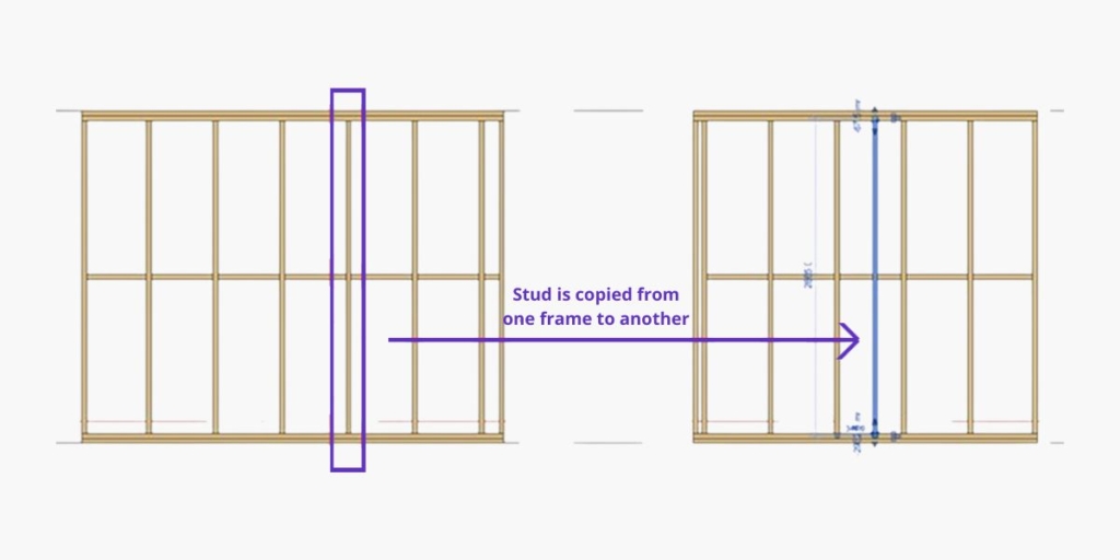
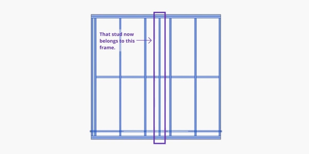
Enhanced ‘Add External Element to Frame’
This command for adding an external element to a given frame now lets you add elements to a frame by copying them from another frame.
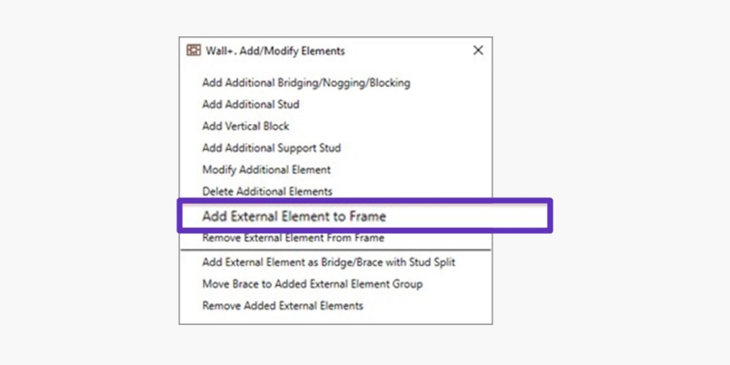
To use it, simply select an element or multiple elements from one frame and copy them to another. Copied elements are recognized as external elements of the frame.
After using ‘Add External Element to Frame’, any copied elements will be included when creating assemblies for shop drawings and schedules.
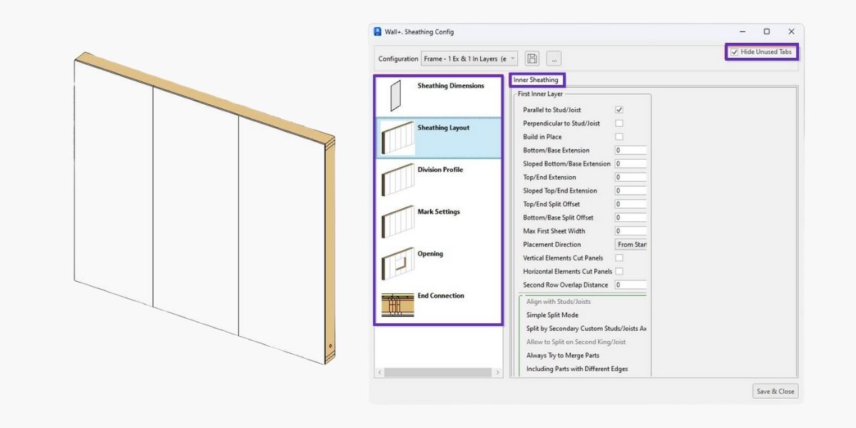
Hide unused tabs
This new feature simplifies the user experience by displaying only relevant information and putting distractions out of sight. When using ‘Modify Sheathing’, only relevant tabs will be displayed; unused tabs will be hidden. In addition, it only shows relevant layers: if the wall has only an inner sheathing layer, then the outer sheathing layer will be hidden.
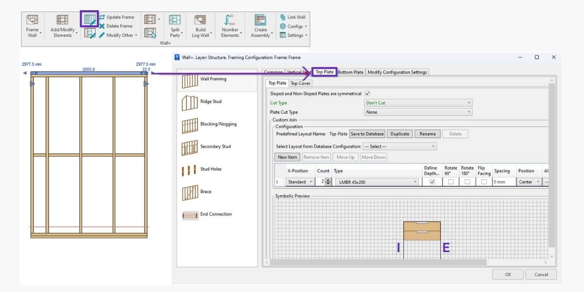
‘Modify Frame’ enhancement
When using the ‘Modify Frame’ function, it will open the configurations window based on the selected element.
For example: If you use ‘Modify Frame’ and select a Top Plate, then it will open the ‘Top Plate’ tab of the Framing Configurations straightaway.
Select elements by filter
This new feature allows you to create a selection filter based on chosen parameters and their values, saving you valuable time and effort when selecting the desired element(s).
No more tedious manual selection – simply set your desired parameters and let the software do the work for you.
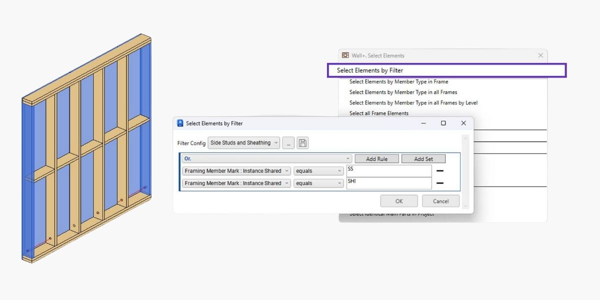
By the way, it is not limited to structural framing elements: it works for Parts, too.
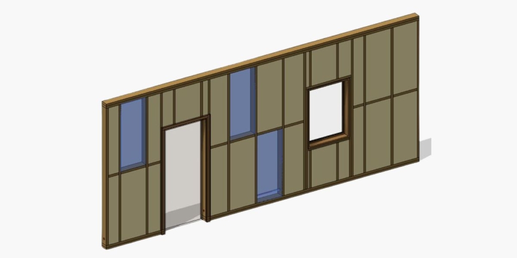
Enhanced sample paneling ‘Insulation’ configuration
This feature lets you split insulation parts exactly with the studs and plates in a wall frame. The automated process of splitting insulation parts according to the underlying studs and plates provides a streamlined and effortless solution that can increase productivity and reduce costs.
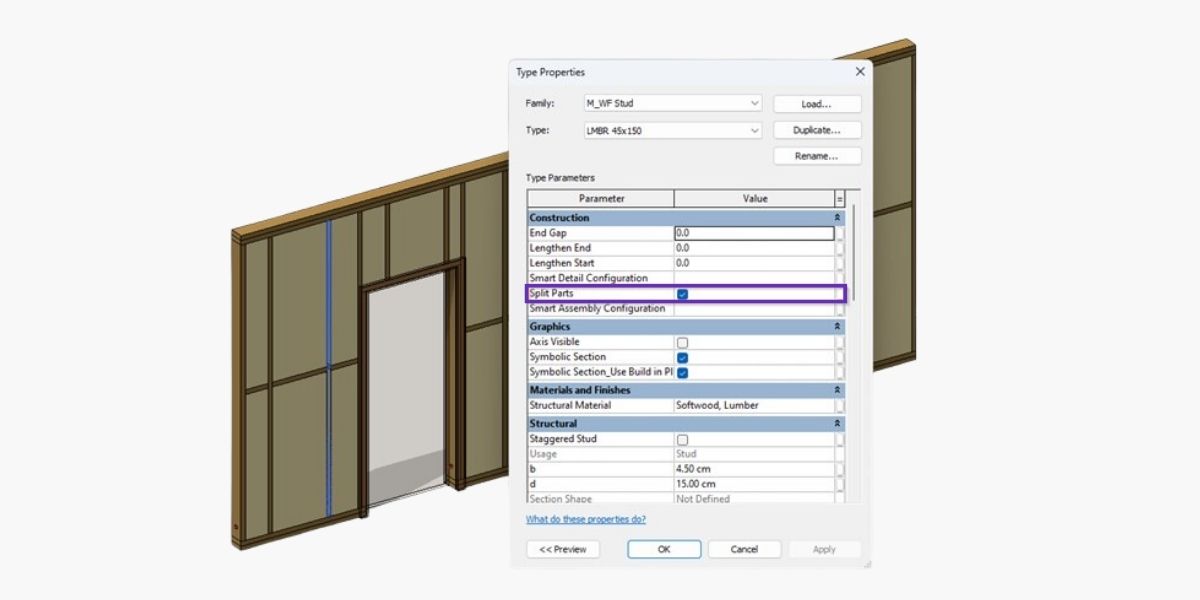
To make this work, you have to turn ON the ‘Split Parts’ Type Parameter and the ‘Cut with Voids when Loaded’ option in the Revit Family Editor for Stud and Plate families that need to be split and have Parts cut.
Here’s where to find those tick marks.
‘Split Parts’ is in the Type Properties of the stud and plate that should split the insulation:
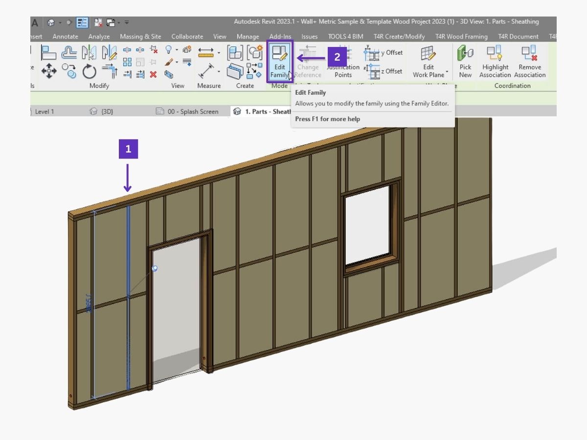
To turn ON the ‘Cut With Voids When Loaded’ instance parameter for the stud and plate families, select the desired family and click the ‘Edit Family’ button:
Then, in the family template, turn ON the ‘Cut with Voids When Loaded’ instance parameter.
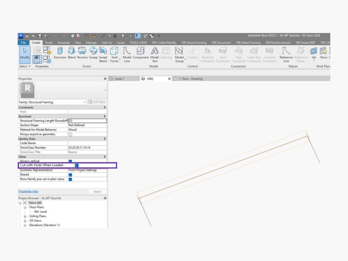
Once you’ve done those steps, insulation should be successfully split into parts by studs and plates when splitting.
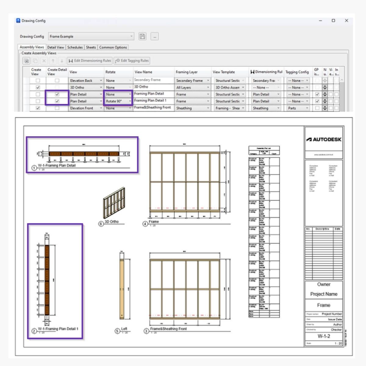
Rotate detail views
We’ve made it so that you can rotate detail views in the Shop Drawing Configuration! With this enhancement, you have complete control over the orientation of your detail views, making it easier than ever to create professional and visually engaging shop drawings.
Here is an example of non-rotated and rotated detail views on a sheet:
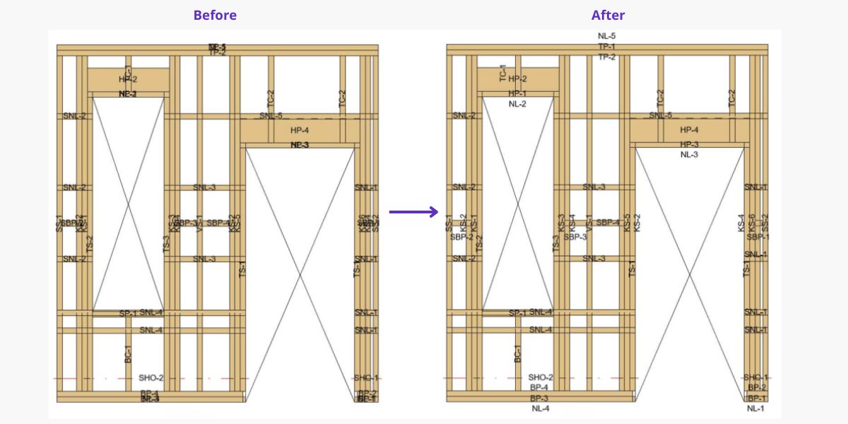
Avoid tag overlap
You now have a greater range of options for how you want your tags to behave, allowing you to effortlessly create a clean and organized layout. Use the ‘Avoid Tag Overlap’ options to set up how tags should be displaced so that they don’t interfere with each other.
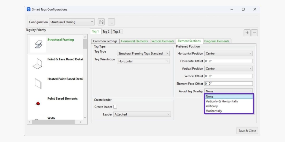
Here is an example of how it can affect your tags:
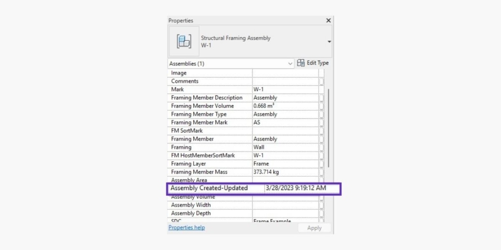
Auto-fill ‘Assembly Created-Updated’ instance parameter
This enhanced feature automatically fills in when your assembly was created or last updated, giving you instant access to this valuable information. Easily track the history of your assemblies and stay on top of updates!
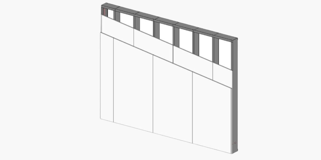
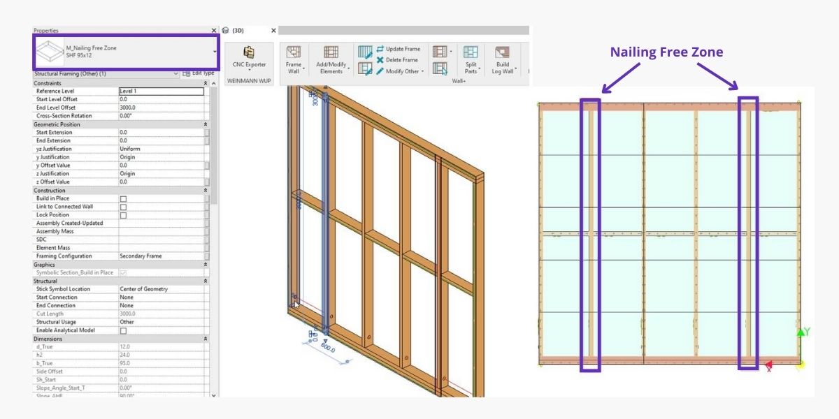
Secondary frame for sheathing
Now it’s possible to create a secondary frame for your sheathing layers, giving you even greater versatility and control over your framing layer.
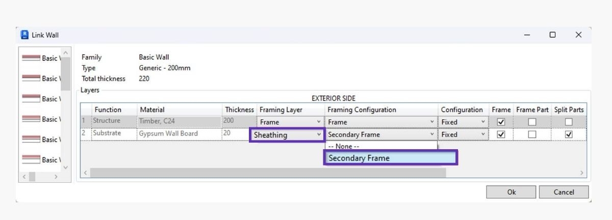
With this new feature, you can easily create custom framing configurations that meet your unique needs and preferences when it comes to sheathing layouts.
It comes in handy when dealing with CNC WUP and CDT4 exporters. For example, Nailing Free Zone families can be placed in the secondary frame configuration and create nailing exclusion zones for sheathing.
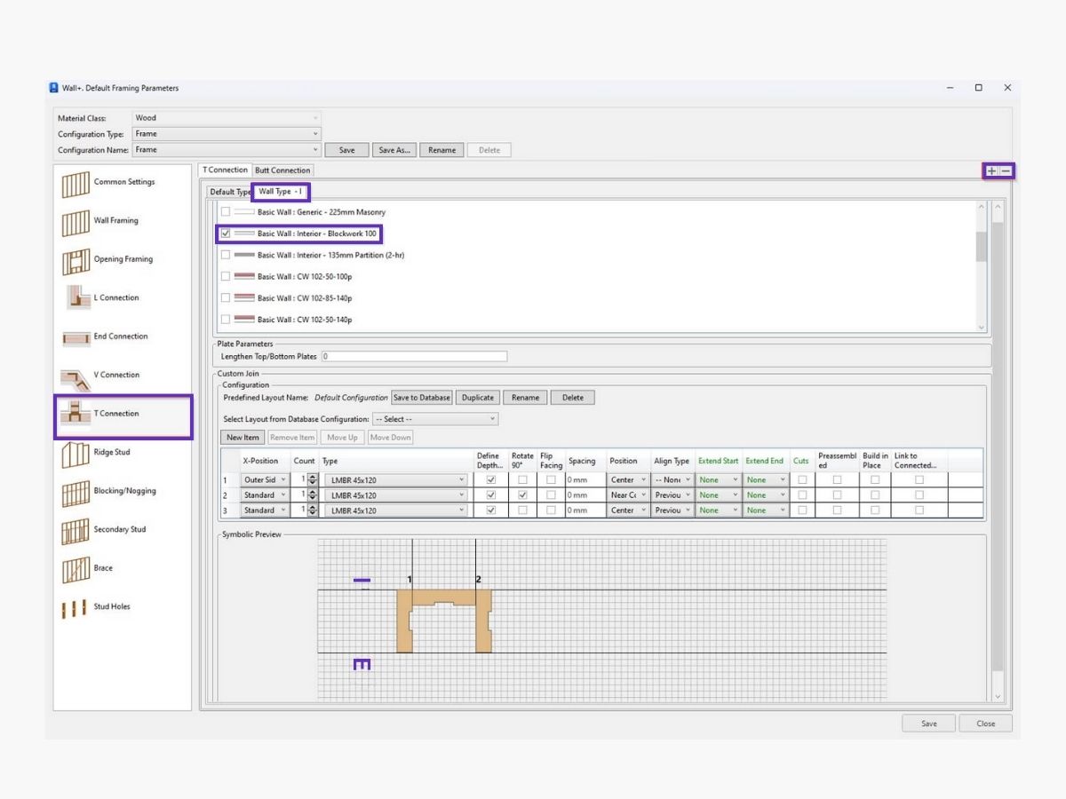
New feature for T connections
Using the updated T connection offers a much wider range of options for customizing your T connection to match the specific type of wall being used. This allows for greater flexibility and adaptability for framing.
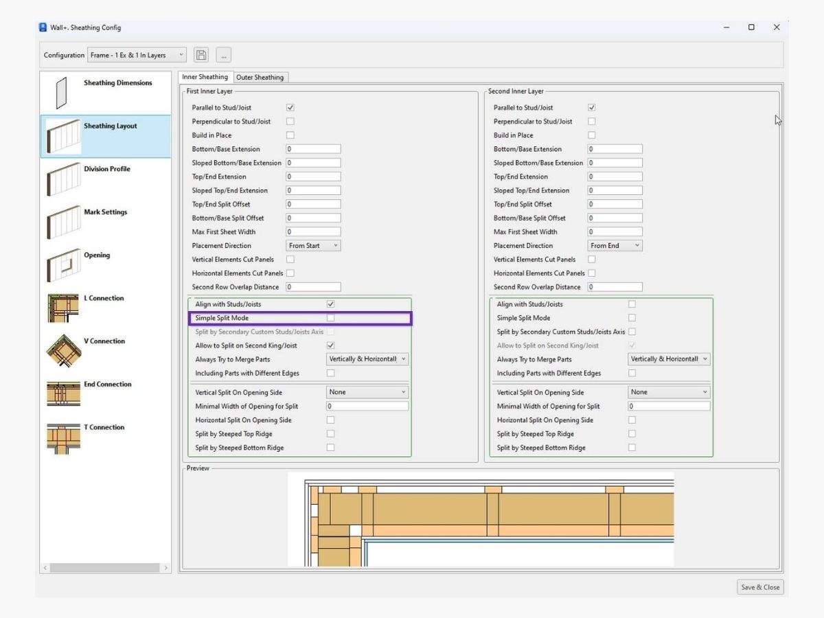
New feature: ‘Simple Split Mode’ in Sheathing and Paneling Configuration
The ‘Simple Split Mode’ disables the merging of parts, significantly decreasing the time required to split parts, particularly for walls, floors, ceilings, or roofs that have large areas. This is especially valuable in situations where numerous small panels must be split.
New ‘Staggered Part Split Stud-Joist’ families
The new Staggered Split Stud Families extend the capabilities of automated paneling splitting where part layers should overlap vertically at every second stud.
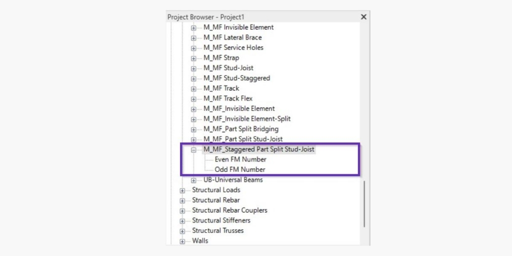
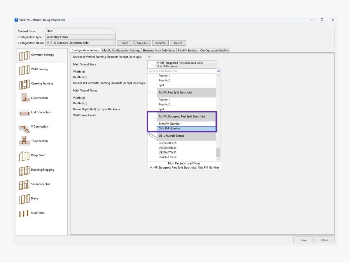
Note! If you’re looking to unlock the full potential of these families, it’s crucial to incorporate them as the Main Type of Stud in your Secondary Frame configurations.
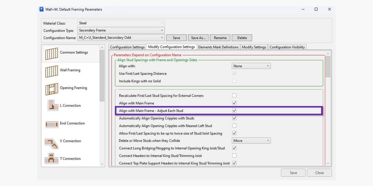
But that’s not all – we’ve also introduced a new feature that enhances the alignment of your secondary frame families with your main frame families, specifically for situations where split studs should be staggered.
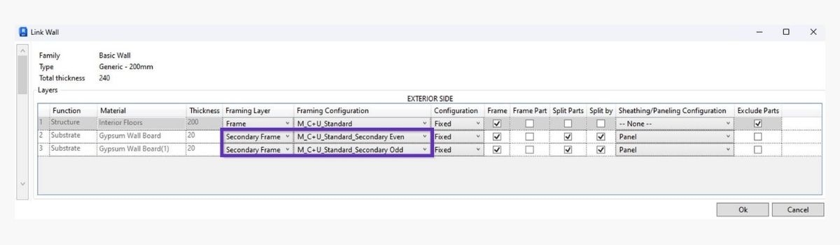
One important reminder – don’t forget to link your secondary frame configurations with the wall! This crucial step ensures that your construction components are properly integrated.
Last but not least, don’t forget to enable ‘Vertical Split by “Split Part”’ in the Paneling Configuration.
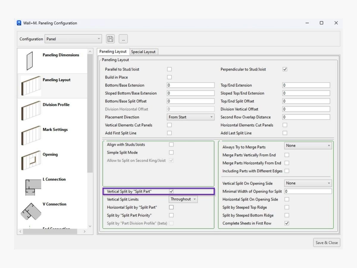
With Vertical Split enabled, you’ll be able to split and overlap your panels with ease, resulting in a flawless and seamless finished product, like this example in which overlapping paneling layers are cut by every-other stud.