Our Wood Framing and Metal Framing BIM software for Revit has gotten another round of new features. Among the latest enhancements: more flexibility to control brace groups (including adding partial brace groups and allowing braces to run across openings), separate preassemblies for joined openings, special layouts for paneling, and to align the secondary stud system with the Project Base Point.
Let’s get into the new features that have been included in the latest version.
Separate Preassemblies for Joined Openings
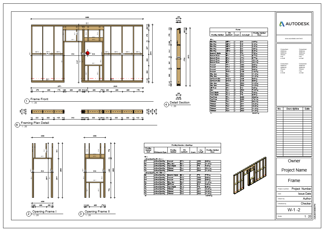
This feature lets you make separate preassemblies for openings that are part of a joined opening — and the preassemblies will exclude other elements (like top plate supports, etc.) that extend across the joined opening. You can find this option to create separate preassemblies for joined openings in the ‘Modify Configuration Settings’ tab of the Default Framing Parameters window:

In this example of a joined opening consisting of a door and a window, we want a separate preassembly for the door and another for the window. Since the top support runs the width of the joined opening, it will not be included into either preassembly.

Later on down the road, you can use the Wood/Metal Framing software to create separate shop drawings and schedules automatically, with the help of Revit Filters:

Full Sheet:
Transportation Braces
In the latest version of our framing tools, you can add transportation braces that run across openings. To allow this, just tick “Allow Brace and Opening intersection” in the Framing Configuration:

That’ll let you add bracing that runs across the openings:

Align Secondary Stud System with Project Base Point
With this latest version of Wood/Metal Framing, you can align a Secondary Stud system with the Project Base Point. In the past, this feature was available only for the Main Frame.
With the ‘Align with Project Base Point’ feature, you can space and align all studs at the same time. Project Base Point now handles positioning in a more robust manner: instead of directly defining the spacing only between the studs, you also define the grid spacing, and the function takes care of the rest. Studs from the Main Frame and Secondary Stud system are positioned on the gridlines, so that they always match throughout the whole project.
Notice how the studs of both the Main Frame and the Secondary Stud system are spaced according to the grid:

How do you use this new feature? The first step is to unclip the state of the Revit Project Base Point and move it to the needed position:

For more convenience, turn Revit Work Plane’s visibility ON and move it to the Project Base Point.
It will help you determine whether the studs or joists are created in the right position.
Finally, turn ON ‘Align with Project Base Point’ in the Framing Configuration dialog:

And frame!
Additional control over Brace Groups
More features have been added to Brace Groups allowing you greater control over complex combinations.

Partial Brace Groups
A new feature called Partial Brace Group lets you create what we call a partial brace group. To use this feature you need to select four elements as bounds for the group: so two studs and two horizontal elements. That way the Brace Group will be created only between those four elements (not the whole height between studs).

Special Layouts for Paneling, additional Splitting Options
With this new version of Wood/Metal Framing you’ve got more possibilities for paneling. To wit, you can ‘Enable Special Layout’ and choose between available Split Types:

For example, if we select ‘Split by side of openings’ and enter ‘Minimal Distance’ and ‘Minimum Width’ values for windows, doors, generic openings, and system openings as shown in the Special Layout tab below…

…we can get a result like this:

Minimum dimensions for framing openings
In the newest versions of our framing software for Revit, you can enter minimum dimensions for openings that should be framed:
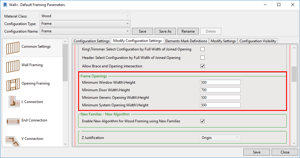
If an opening’s width or height does not meet the threshold, then that opening will be ignored in the framing process:

Toggle visibility of configuration types
Lastly, there’s a new option that lets you control whether or not (and which) Configuration Types are visible. Visibility was added to Wood Framing Wall+, Floor+ and Roof+. That means you can turn off the visibility of unneeded configuration types (Secondary Frame, Nailers, Sidings etc.), and they won’t appear in the “Framing Configuration” and “Link Wall” windows.