Framing professionals from around the world who use our BIM solutions for timber and steel framing in Autodesk Revit are in regular contact with us, letting us know what their needs are and giving suggestions on how the tools can be further enhanced.
The latest version of our Wood Framing and Metal Framing design software for Revit incorporates their requests to be able to control top and bottom cripples independently, to be able to manipulate top and bottom plates in wall-to-wall connections, to have increased functionality for modifying sheathing and paneling, to add some dimensioning options, and more.
Let’s go through the updates that have been made in the latest version of Wood Framing and Metal Framing.
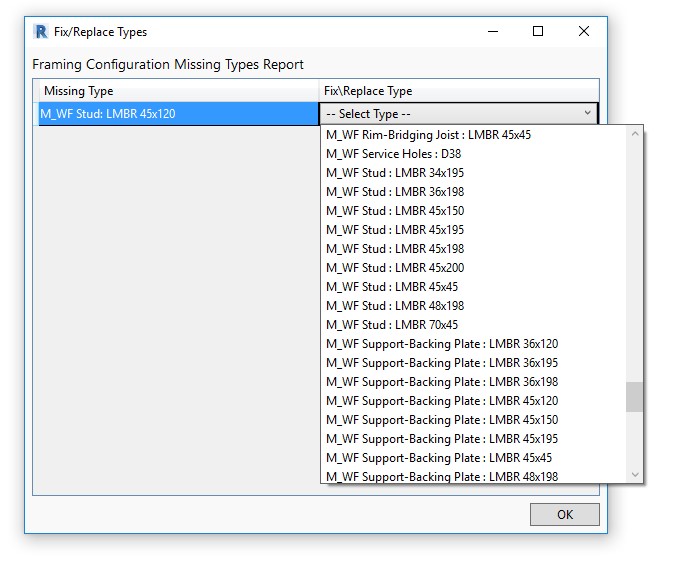
An addition to the Missing Types Report
At the bottom of the Missing Types Report window, there is now a button named ‘Fix/Replace Types in Current Configuration’.
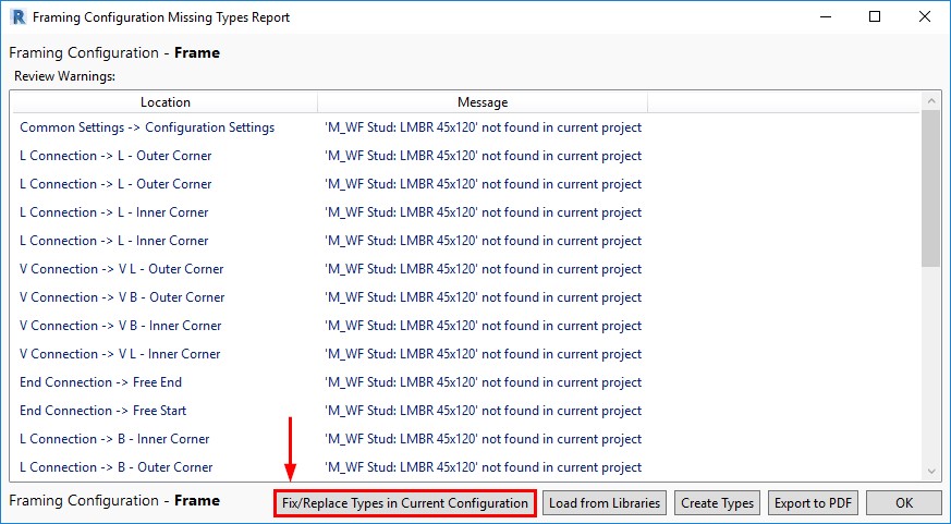
This new option lets you quickly place missing families or types in the project, making the Missing Types Report much more useful because you can efficiently resolve the issues that it finds.
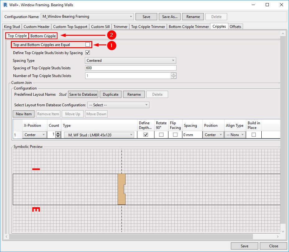
Better control of cripples
Window, Door, and Opening Cripples have been separated into Top Cripples and Bottom Cripples. After you untick ‘Top and Bottom Cripples are Equal’, two tabs will appear for creating Top and Bottom Cripple layouts. And you have additional flexibility in creating Custom Joins with the help of the symbolic preview window:
Database configurations can be linked together
The newest version of the software makes working with Database Configurations more efficient because you can link configurations together throughout all parts of your framing configurations to reflect changes made to any one database configuration. You can find this setting in the Modify Settings tab. Tick ‘Enable “Update by Database” in Custom Joins’.

Then, a new column – Update by Database – will appear in all Custom Joins. Below, for example, you can see the new column in the Window Framing tab:
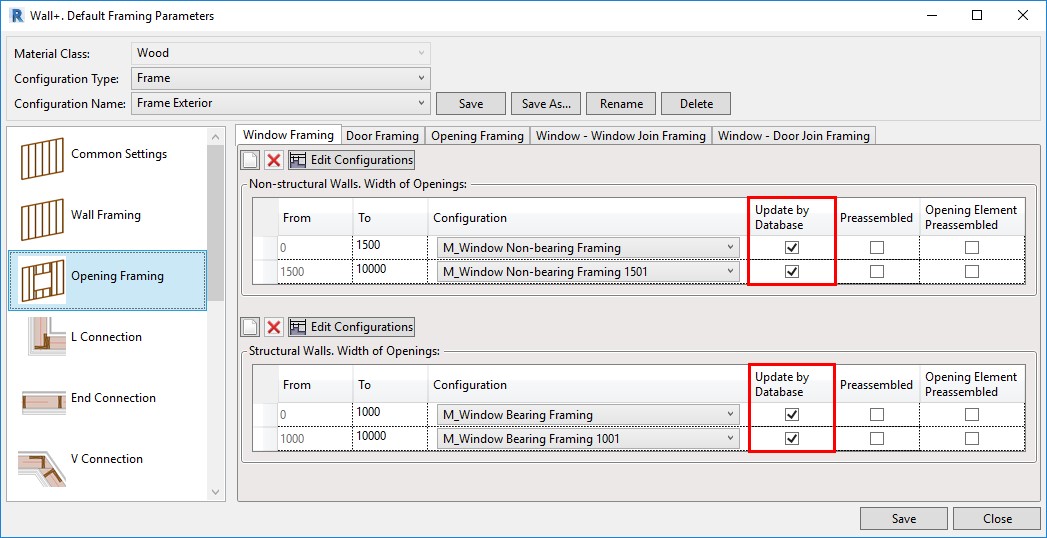
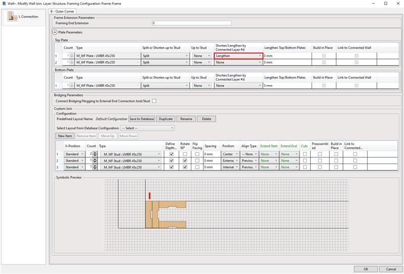
Plate connection control
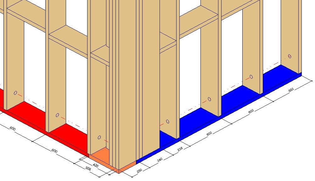
In the newest release, the efficiency of controlling top and bottom plates in L, End, V, and T wall connection types has been increased. This new feature allows you to fully control both top and bottom plates in wall-to-wall connections and brings more independence to each plate behavior within the wall frame. Wall plate assemblies consisting of single or multiple plates can be cut short, extended, or split up to a selected wall stud. Alternatively, you can input values and lengthen or shorten plates to a specific dimension. It delivers more control and versatility to complex wall-to-wall connection types and adds another layer of control to the already extensive set of L, End, V, and T configuration parameters.
In this example, you can see the setting used an L Connection:
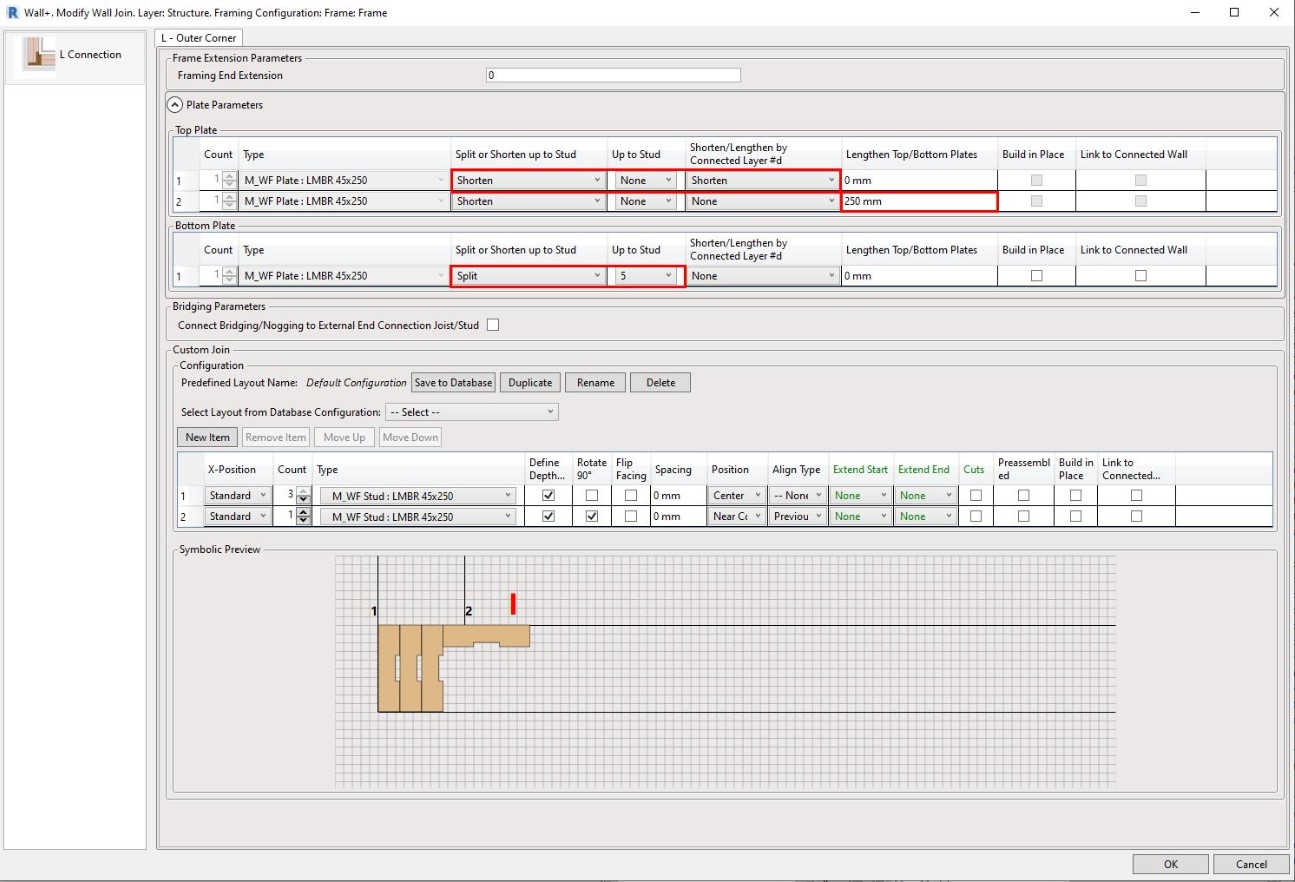
Result – Top Plate:

Result – Bottom Plate:
Increased Split Elements functionality
Acting on customer requests to expand the Split Elements tool set so that they could delete elements that have already been split, we have added a new command that allows you to delete splits and delete bridging/nogging elements that have been split. When dealing with bridging/nogging elements, like horizontal siding, you can now delete unwanted siding board cut offs using the ‘Delete Plate or Bridging/Nogging’ command from the Cut/Delete/Move/Rotate Elements menu.

Result:
Opening Configuration by the Family Type
A possibility to control the Opening Configuration by the family ‘Framing Configuration’ text parameter has been added to the newest releases of our framing software. After entering an Opening Configuration name in the Type Parameters, the opening will be framed based on the rules of that configuration, instead of the one that is mapped in the Wall Link:
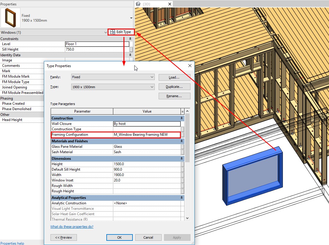
That way, you can frame openings based on their Family Type, and not just their width as was previously the case.
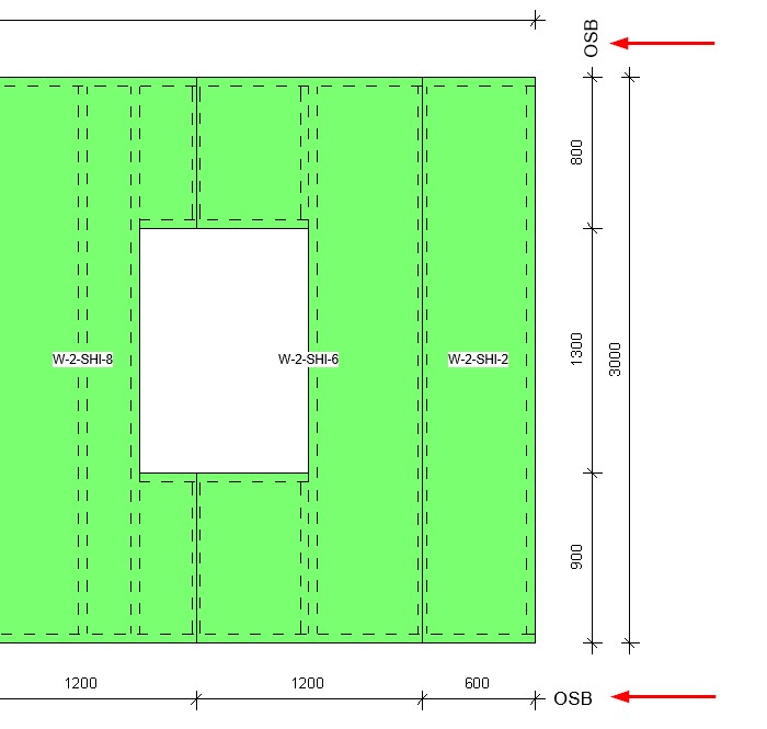
Reconfigure sheathing and paneling
Another great update is the ability to modify sheathing and paneling by choosing a different configuration:
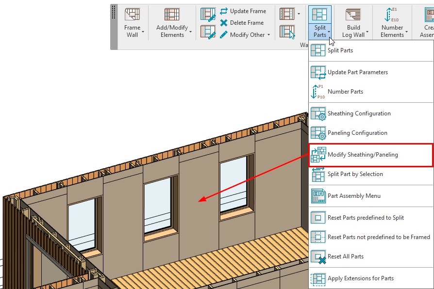
Before the update, you could only modify the configuration that was used to split parts, but now you can select a different configuration for Sheathing/Paneling:

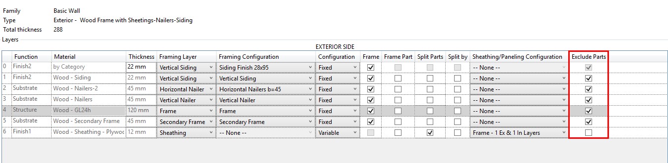
Create or exclude parts with Frame Wall
Controls have been added so that you can create or exclude parts with the ‘Frame Wall’ command:
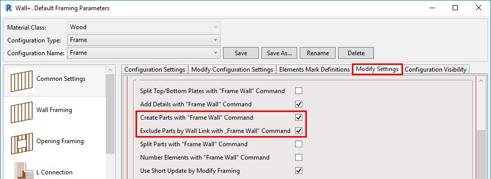
If ticked ON, then the parts will be created or excluded with the ‘Frame Wall’ command, based on the settings in the Wall Link:
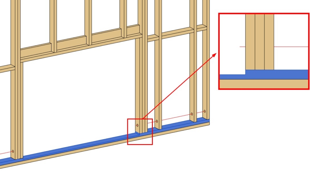
Cutting bottom plates with a void
A new option for cutting Bottom Plates with a void in an Opening family has been added in the ‘Modify Settings’ tab:
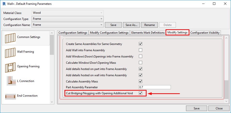
If ticked ON, then Bottom Plates will be cut by intersecting Opening families that have a Void in them:
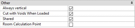
Note, that ‘Cut with Voids When Loaded’ must be ticked ON in the Opening family:
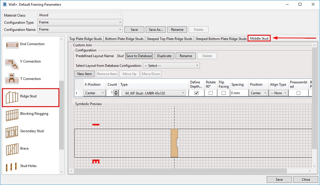
Mid-ridge stud
Another client request has come true with this enhancement. A new option in the Ridge Stud tab has been added to the framing tools: ‘Middle Stud’ – it’s for adding Studs in the center of the Wall automatically:
Preassembled openings
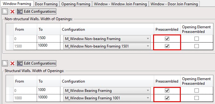
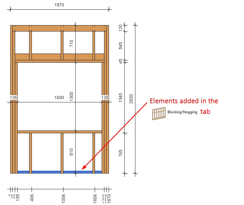
This improvement will be useful for those who work with preassembled openings. Elements that you add through the ‘Blocking/Nogging’ tab and that have Placement limits set to Openings (Windows, Doors, etc.)…
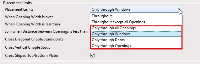
…will be added to the Openings Preassembly automatically if the Opening is marked as preassembled:
Result:
Add more tabs for dimensioning rules
From now on, you can create dimensioning configurations in multiple dimensioning rule tabs for same-category elements:
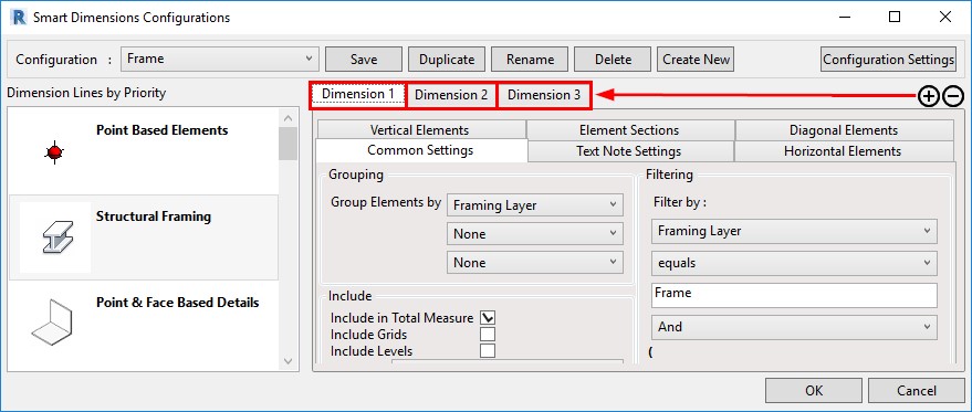
That will lead to more options and flexibility using filters and other settings.
Auto-dimension part openings
In the new versions, you have a possibility to dimension part openings automatically using Smart Dimensions. A new tab named ‘Part Openings’ will appear after creating a new dimensioning configuration:
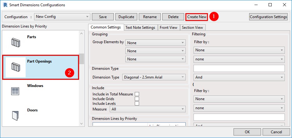
As a result, part openings will have their individual dimensions that are not tied to Structural Framing elements:
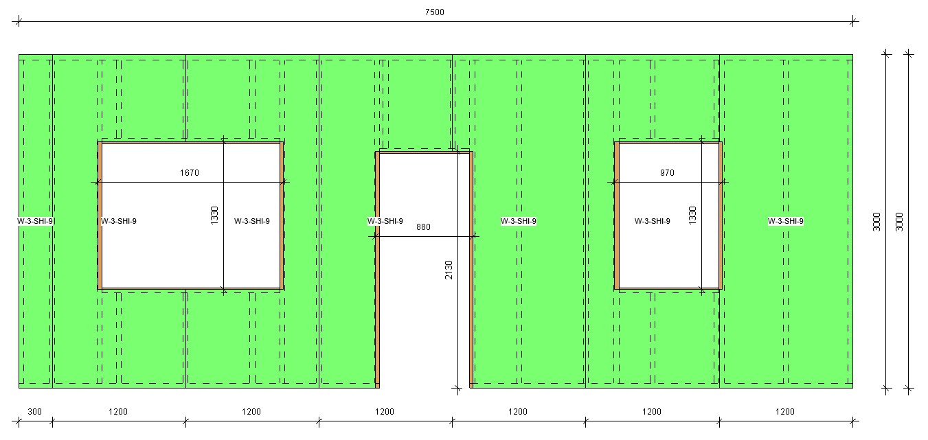
Use material as a text note parameter
A possibility to use ‘Material’ as a Text Note Parameter in Smart Dimensions was added to the newest versions:
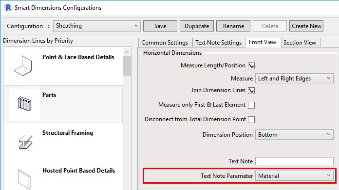
In this example, you can see that the sheathing layer material Name was added to vertical and horizontal dimensions:
Placement of assembly views
We have made improvements on where assembly views are placed. From now on, view positions will be aligned by views placed in the Sheet Template. After creating an assembly for which sheets are going to be used as Sheet Templates, you can modify the positions for, let’s say, Plan and Section views:
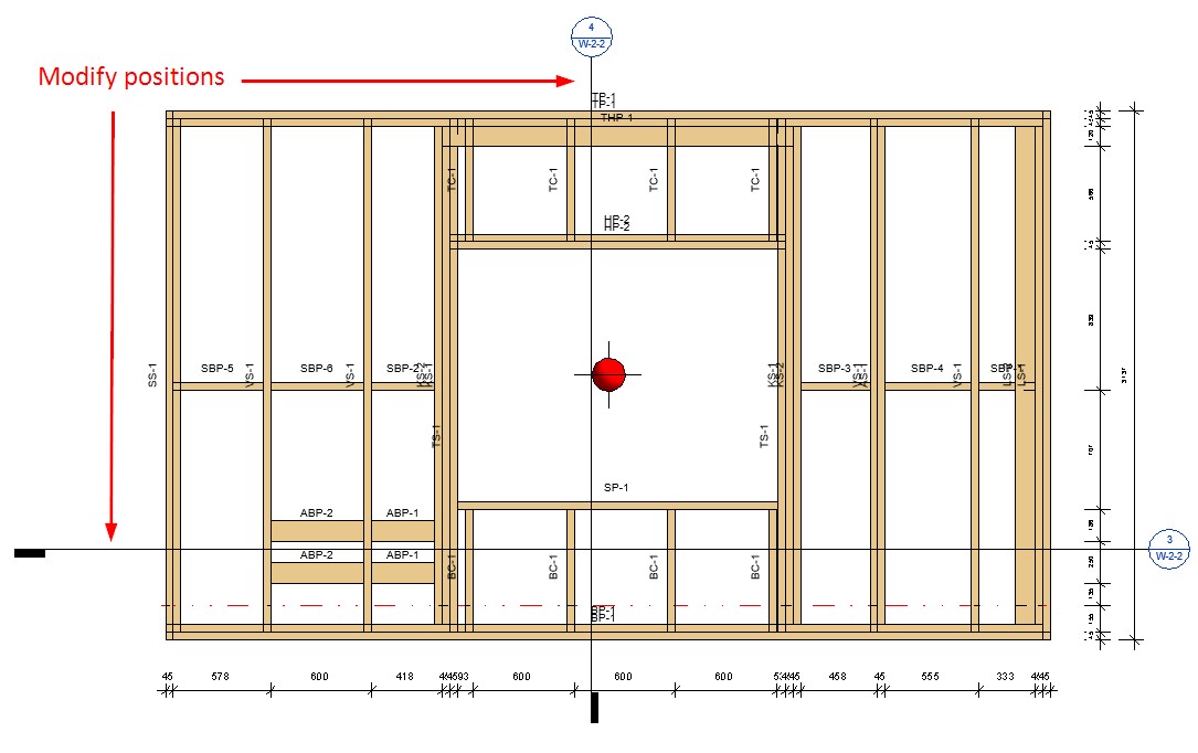
After sheets for this panel are created and set as templates, all future assembly views will be created based on these modified view positions.
Disable analytical lines
Lastly, a type parameter was added that lets you disable analytical lines for specific elements, like service holes and invisible elements:

If ‘Disable Analytical Model’ is ticked ON, then the ‘Enable Analytical Model’ instance parameter is automatically turned off once the elements are distributed:
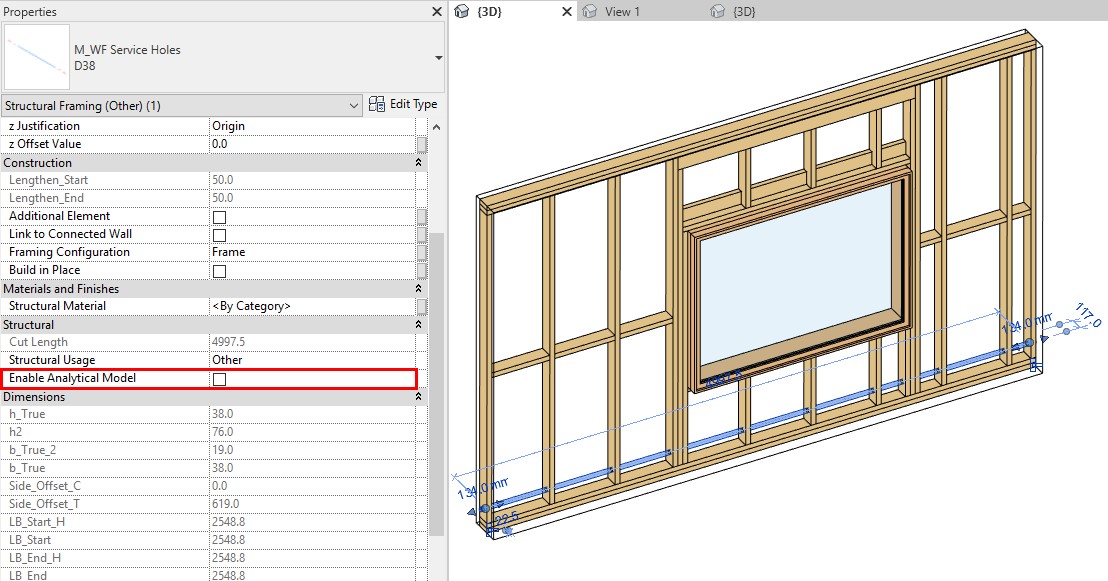
This means that those specific elements will not be exported to, for example, Autodesk® Robot® for structural load analysis.