

Smart Assemblies is probably the most powerful BIM solution out there for automating assembly drawings with dimensions, schedules, legends, and placement of views on a sheet. It’s easy to understand the value it brings for Revit users as hundreds of mouse clicks are replaced by automated configuration settings.
Smart Assemblies receives several updates per year. The newest release of this application for Revit was triggered by requests from a group of clients and to meet some country-specific requirements, but it will definitely bring value to other existing clients as well as new ones.
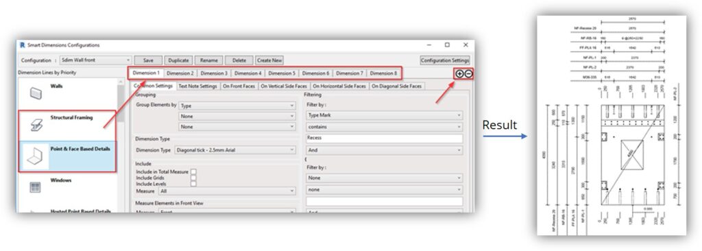
1. Dimensioning rules
Now you’ve got more options for placing dimensions, as the number of rules has been increased from 3 to 10 for Structural framing and Point/Facebased elements. It means more filtering, grouping, dimension styles can be used to dimension elements in the view. This was requested by a couple of clients because of complex dimensioning standards in the precast industry.
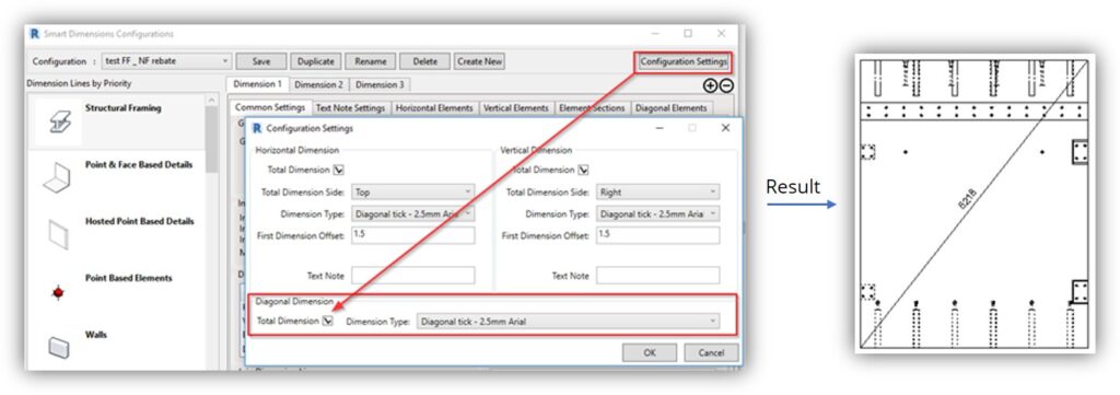
2. Total dimension
This refers to the diagonal total dimension for Walls, Beams, Columns, and other elements. This option is available in the Smart Dimensions Configuration. It works on elements selected to be Included in Total Measure. It’s a popular requirement from Australia-based clients as well as some other countries.
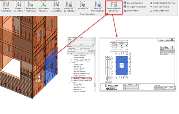
3. Open Assembly Sheet View
Select assembly and go straight to the first assembly sheet using the Open Assembly Sheet View command. Since engineers work with loads of assemblies, it can get quite troublesome getting to the relevant assembly views, so this feature makes it much easier.
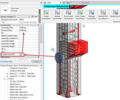
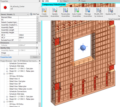
4. Exclude from Gravity Point calculations
Gravity point – you can add a specially named Yes/No parameter „Exclude from GP“, to exclude elements from assembly mass. Miscellaneous objects may sometimes be part of an assembly, but the mass of these elements should not be included, as our clients from Canada informed us. So this option addresses the hassle these clients and other people in the industry might have to deal with.
5. Gravity Point Coordinates
GP coordinates are calculated and written to Gravity point Family, so you can create a schedule or tag and include this information in your documentation. It’s calculated from the bottom-left corner, just like it is shown in the Front view of the assembly. Revit users from Australia, and probably some other countries, should be happy to take a breath while saving some time here as well.
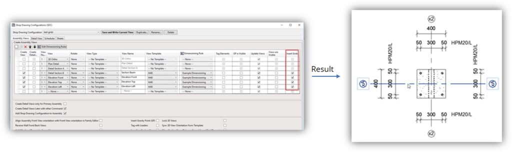
6. Insert Grid
Insert Grid line – now this function will insert the grid line symbol in the assembly view for various elements – Walls, Beams, Columns. Furthermore, they can be not only perpendicular to the front view but to the side view as well. Our partners from Japan work a lot with Beams and Columns, and this is one of their drawing requirements, so it has been covered with this updated feature.
So, we want to encourage the users of Smart Assemblies to try the new possibilities: download the latest version and take advantage of the new possibilities.
In case you’re still not a user of AGACAD products, you are welcome to take a free trial of any of our BIM solutions. It’s easy. Just download the TOOLS4BIM Dock for your version of Revit and select Smart Assemblies or other tool for Revit you’d like to try out.


