We recently received a question from a client in Australia regarding how to use our Precast Concrete solution for Revit to model different types of wall joints, specifically shiplaps.
The Smart Connections feature of Precast Concrete automates this process by placing Revit families according to the configurations set by the user. The families can contain any solids or voids to cut the walls and get them into the right shapes or place connection elements.
In the steps below I show how to create a shiplap joint in a bunch of precast panels all at once using Smart Connections. A similar workflow could be applied to automate the creation of different types of groove joints that are often used by precasters in wall panels too. Because we’re so focused on reducing BIM stress, we make it easier for BIM modelers to get the job done simply and quickly.
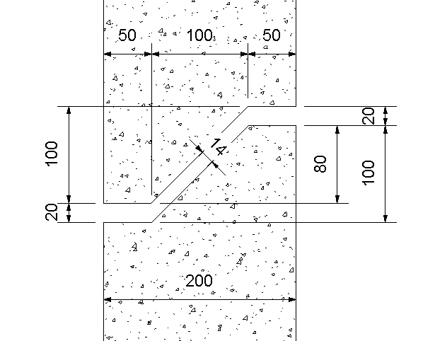
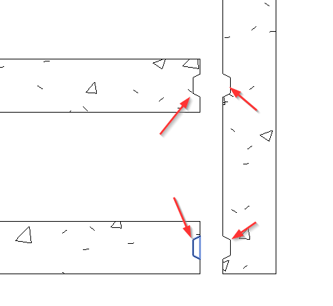
This is the kind of horizontal joint in precast walls that I want to model.
I’ll start the project from a standard template and will use Precast Concrete to create the above shiplap joint in all the wall panels I want. Let’s do this!
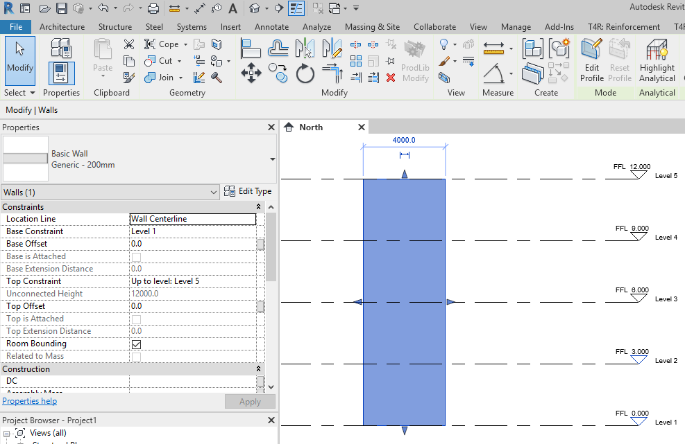
1. Draw a wall and some levels
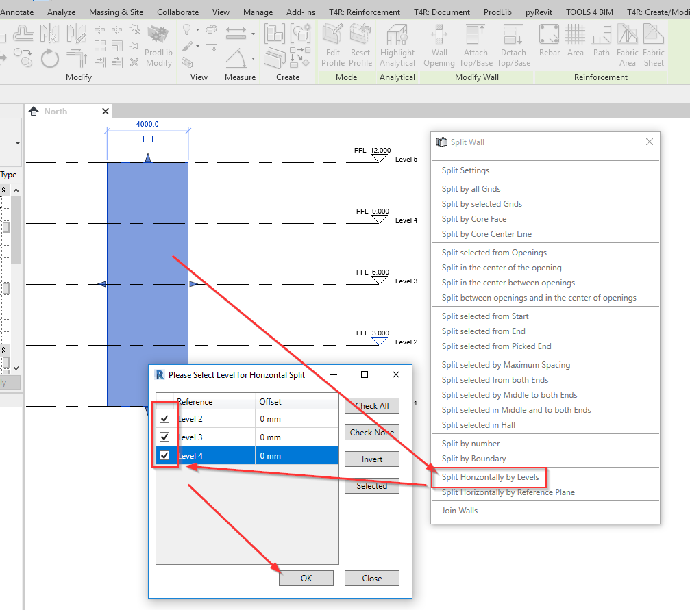
2. Split
Split walls horizontally by using Levels.
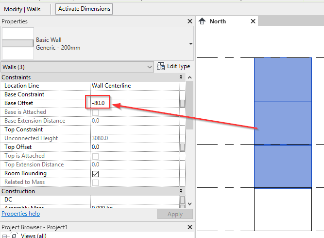
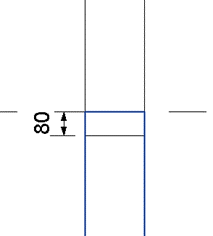
3. Offset
Select walls, starting from Level 2, and add some bottom offset value to make them overlap.
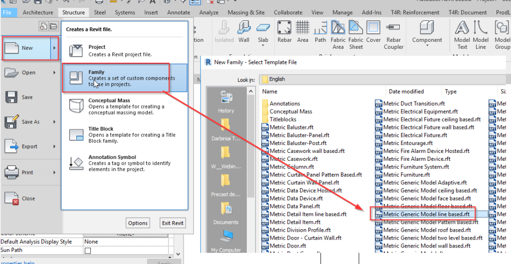
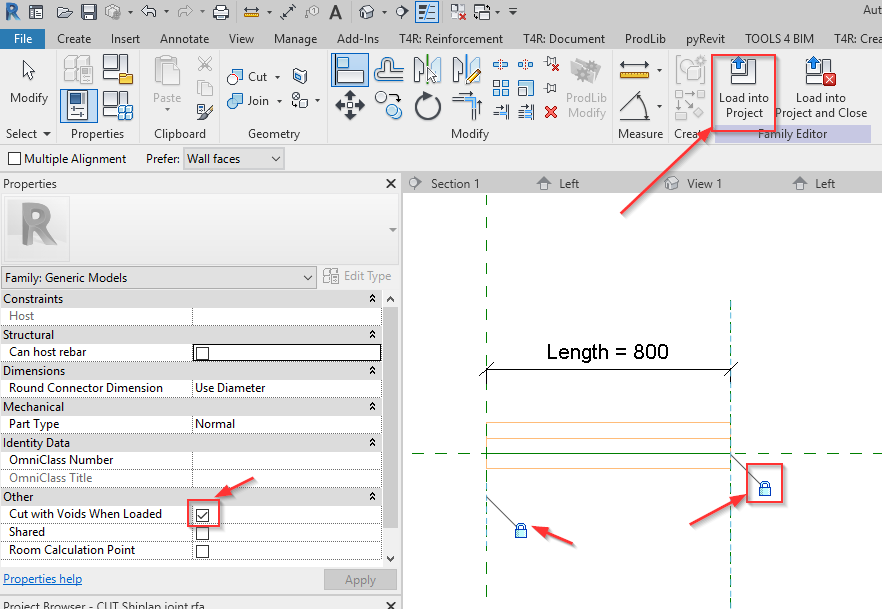
4. Make correct shape
Cut them to get the right shape. To do that, create a line-based family.
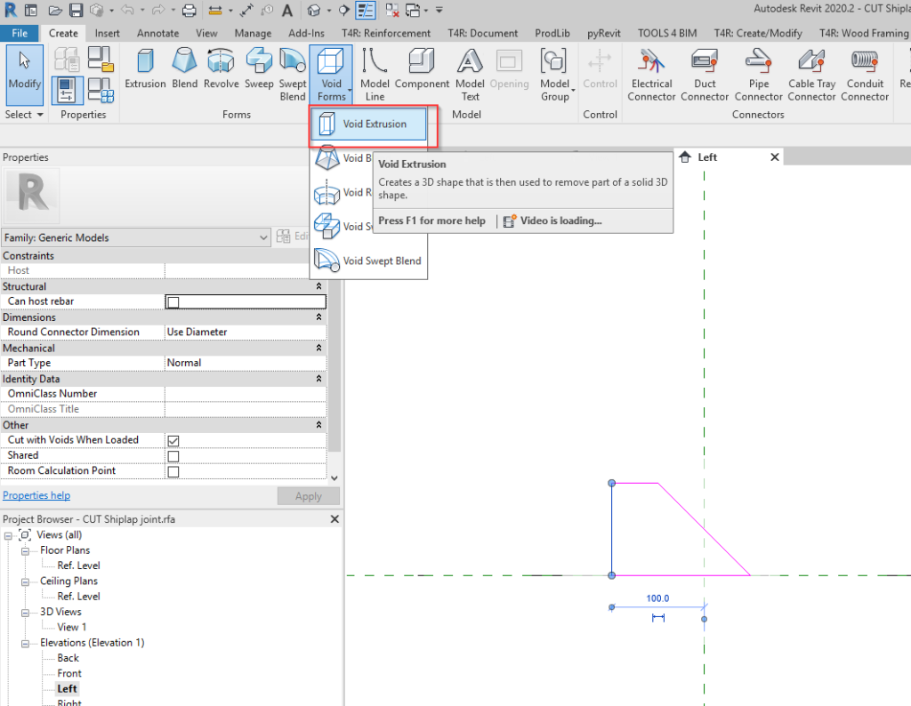
5. Void
Create a void with the required shape.
6. Lock
Lock the ends of it to the correct reference planes, tick ON the ‘Cut with Voids When Loaded’ parameter, Save, and load into your project.
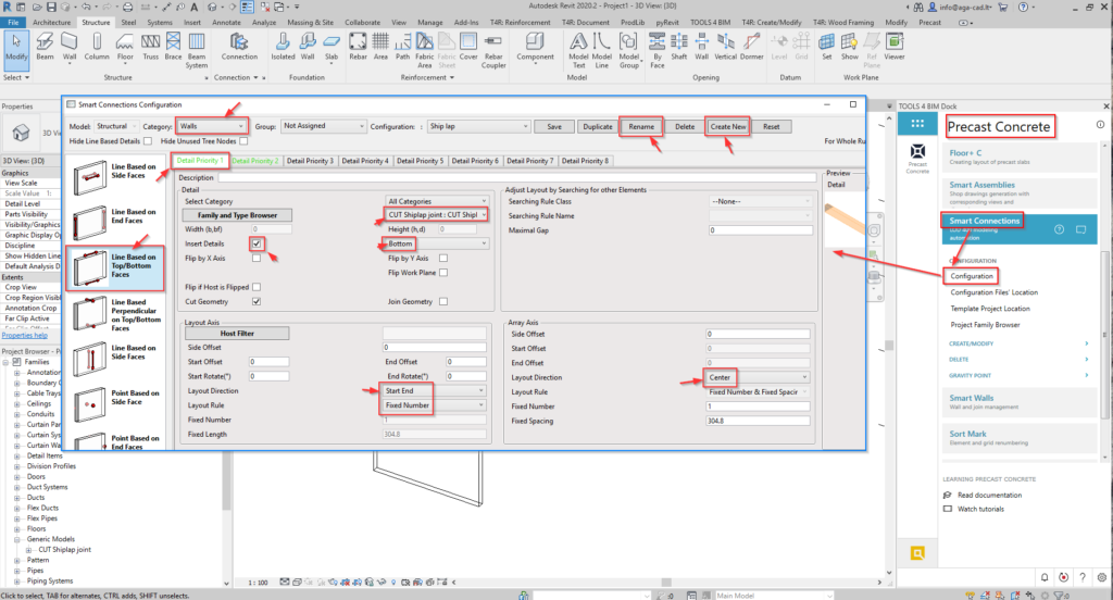
7. Insertion configurations
Insert this Family on all walls simultaneously using Smart Connections. Prepare the configuration like this to cut the bottom.
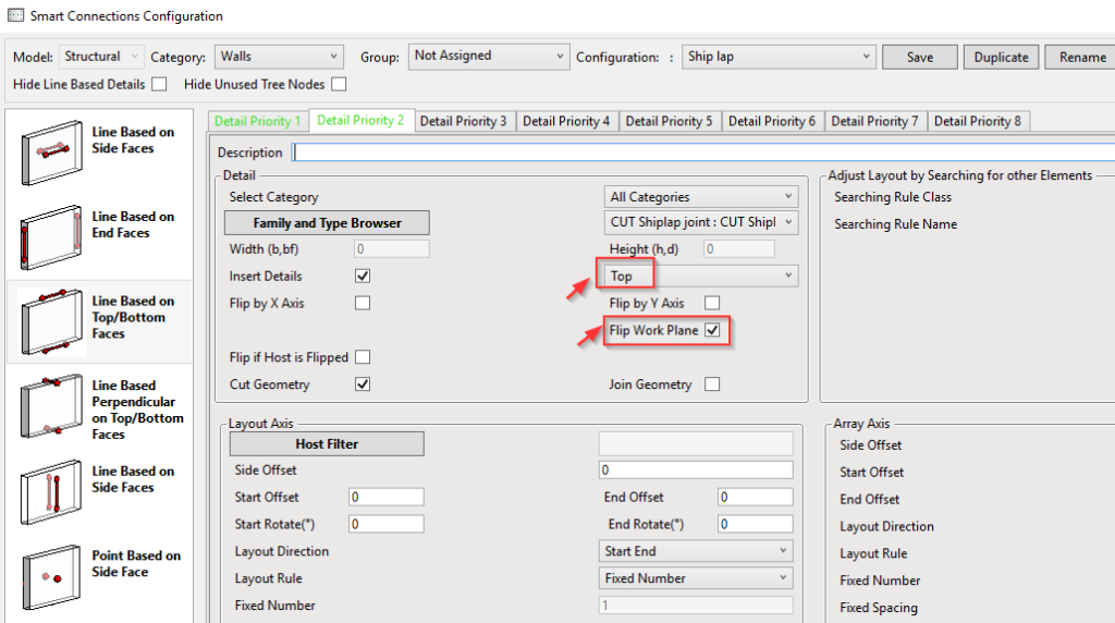
And pretty much the same to cut the top. The only difference is to select ‘Top’ face and turn ON ‘Flip Work Plane’, to make it appear in the correct place:
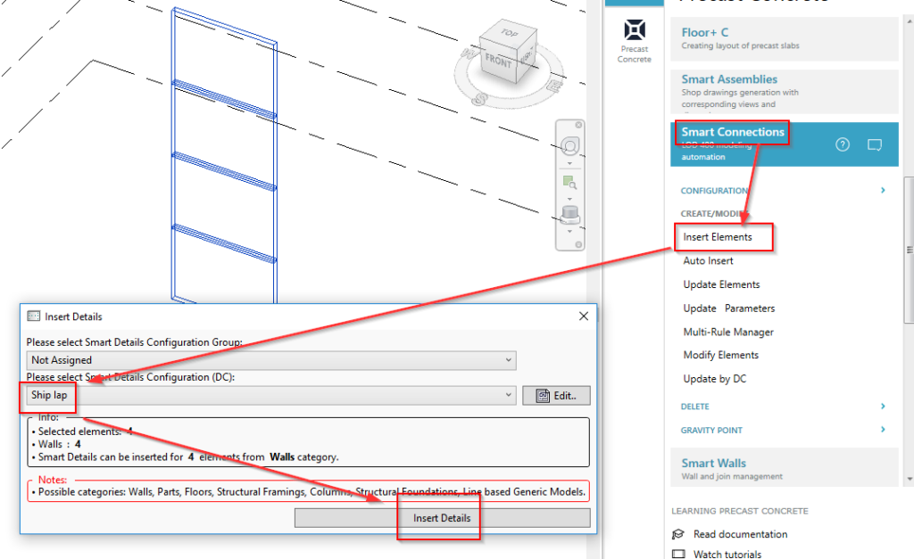
8. Insert
After the configuration is all finished, select all walls and insert the cuts to get the shape of shiplap joint on all walls.
The result looks like this:
You can follow along with how to do this in our video below.
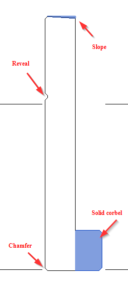
A similar workflow could be used to place solid or void elements, so you could easily apply it on all walls in the project. Other examples could be forming slope, different reveals, solid corbels (supports), vertical cuts, chamfers, etc.
Vertical joints between walls:
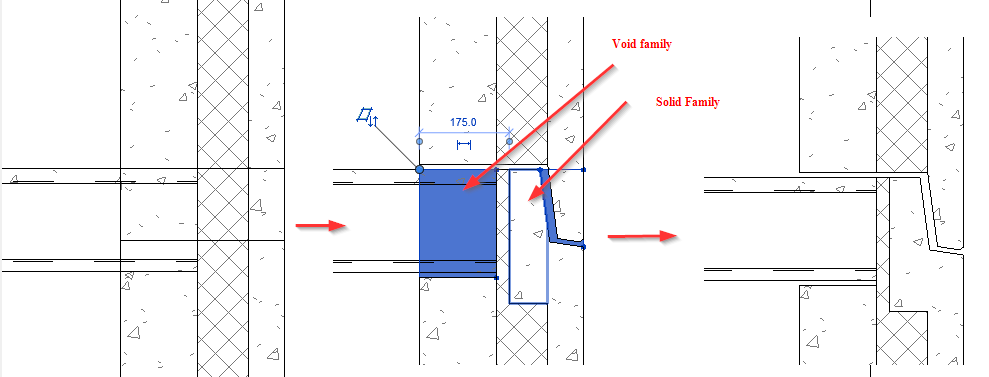
Here’s a more complex example of a precast sandwich wall connection:
So that’s how you can use Smart Connections to model a bunch of shiplap joins between wall panels throughout your precast concrete project in Revit. Current users: Give it a go next time the opportunity arises!