Grout tubes are used in the construction of precast concrete buildings for connecting elements like walls, tilt-up panels, beams, and columns. They’re also known as grout ducts or sleeves.
The way it works is a starter bar (also known as a lap bar or dowel) is precast in one element, say, a wall panel, and then on site that dowel slides into a sleeve that was precast into, say, another panel. The sleeve – typically made of plastic or corrugated steel – is then filled with concrete to form a connection between the wall panels.
Since precast designs can contain quite a lot of grout tubes, placing them is certainly worth automating. That’s where the Smart Connections feature of our Precast Concrete BIM Solution for Revit comes in. It has options that you can configure so that grout tubes will be placed in walls automatically, reducing the amount of time you need to spend on repetitive, manual tasks.
Here’s the workflow that I would recommend. Steps are also laid out below the video.
1. Create family
Create the grout tube family based on a face-based family template. It’s convenient to use such a family in Revit projects because they’re easy to place on any face or work plane. And if you add some voids, you can automatically cut the host element to reduce the concrete volume.
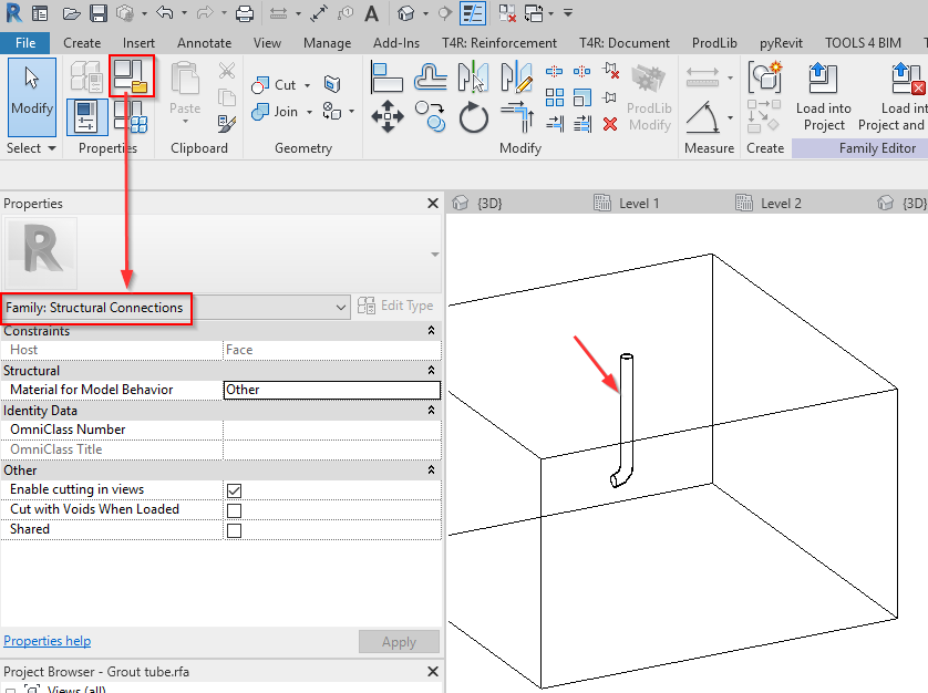
To create the needed geometry, just draw the sweep, add some parameters to control its size, and assign a profile family. Alternatively, you can draw the shape of the tube:

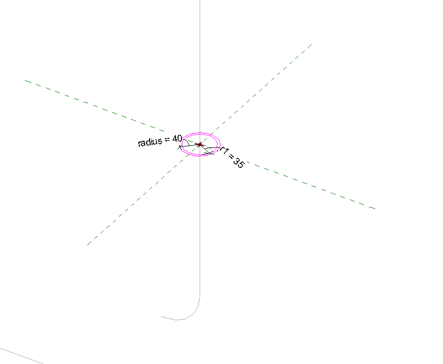
You can also add a similarly shaped void inside the family, which would cut the wall every time you place the family on it. After you have added the shape of the grout duct and cut, save and load it into your Revit project.
2. Open configurations
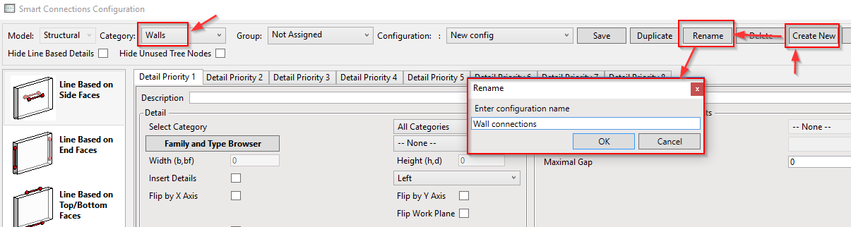
Open the configurations of Smart Connections and define a new rule to place sleeves.
3. Define rule
Define rules for how this point-based family should be placed on the wall.
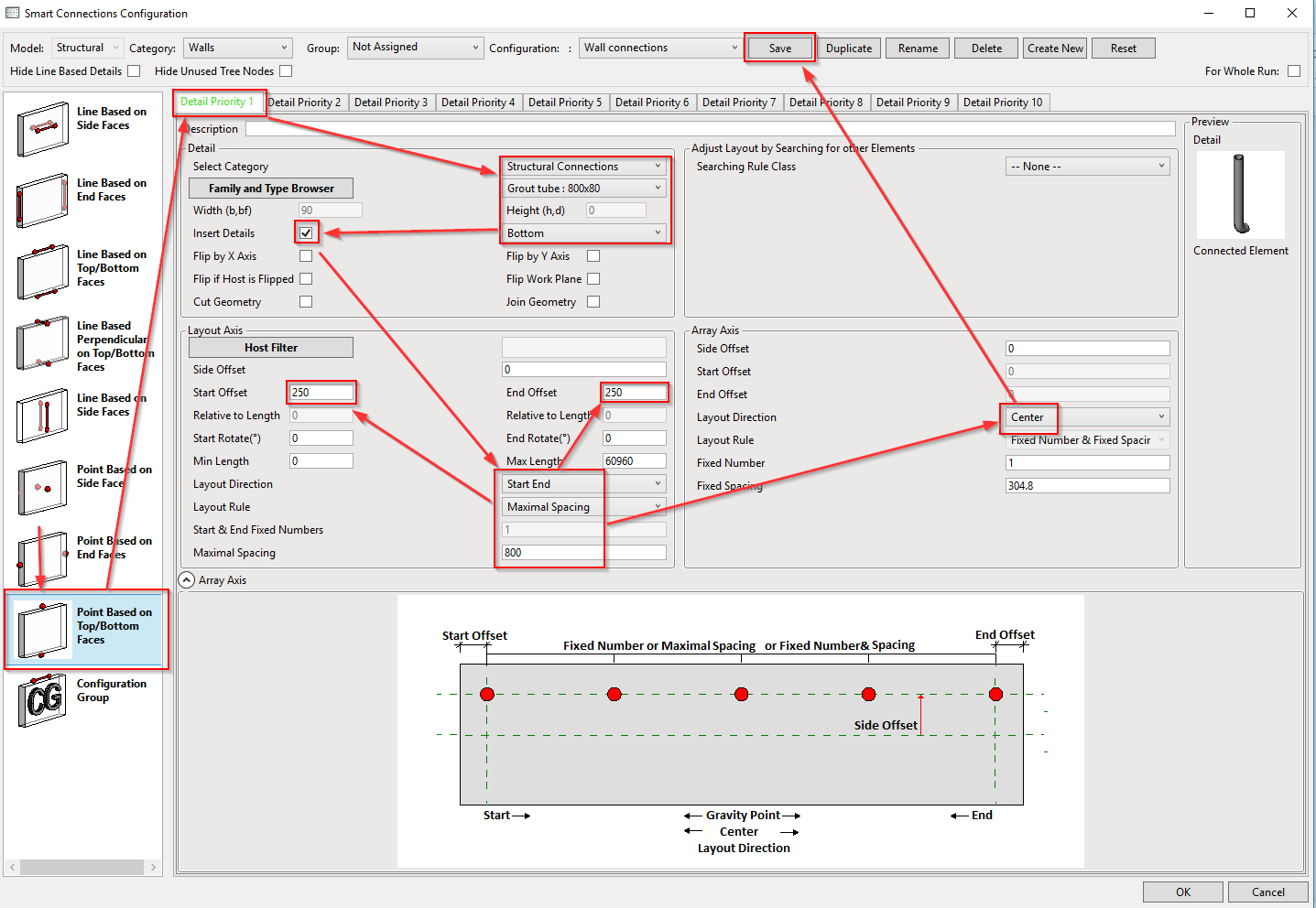
Go to the relevant tab of point-based elements. Select the family you’ve created, tick ‘Insert Details’ ON, and define layout rules along the bottom face of the wall.
In the configurations below, I have selected to place them by Maximum Spacing with some Start and End offsets. In the other direction, I opted to place the grout tube family at the center of the bottom face of the wall. After the settings are defined, save the configuration and you are ready to place them.
4. Insert details
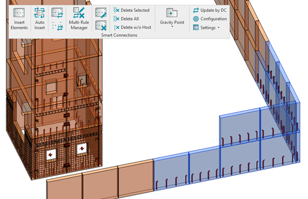
Select walls, click ‘Insert Elements’, select the configuration, and click ‘Insert Details’.

5. Result
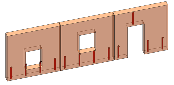
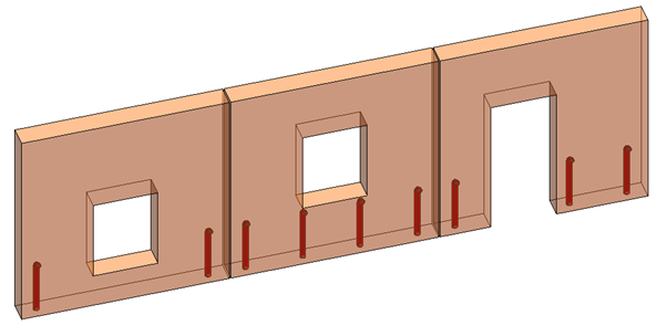
Now all the families for grout filling will be distributed along wall bottoms according to the predefined rule.
Note that if you have doors or windows with low sill height, some tubes may protrude into the opening when applying the current configuration.
So, there’s one more thing that we can do to improve this configuration. Smart Connections has a feature that causes details to adapt to different situations automatically, based on a search of wall connections, intersections with other elements, etc. In this case of low sill height, you can set the solid depth that should be available for the grout tube family to be placed:
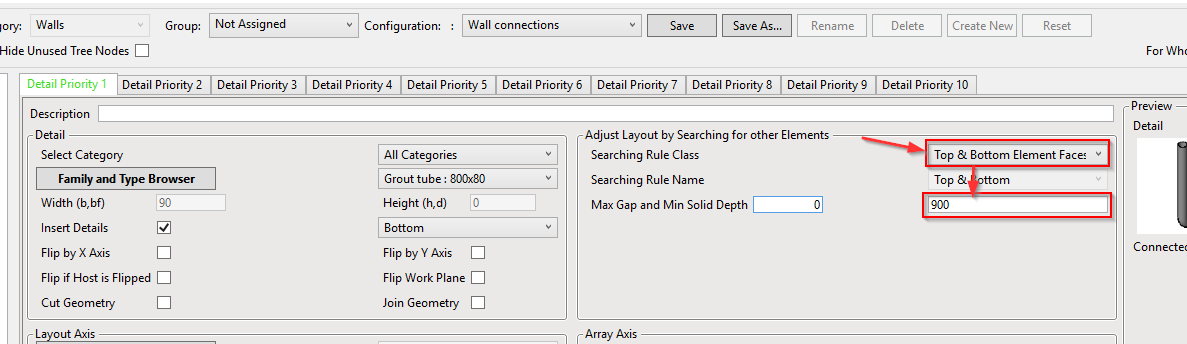
Now this is the result we’re looking for. Grout tubes are not placed where they don’t fit.
After placing, all families may be moved, copied, modified for only the selected wall, or updated if something changes. Also, by using Revit and these individual families, you will automatically get element quantities, in this case the amount of grout tubes.
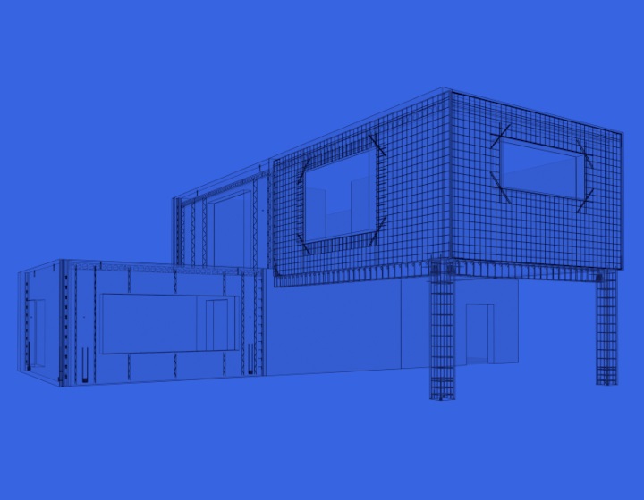
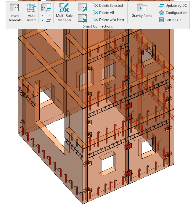
By working on the families and configurations even more, we can further improve automation by placing not only grout ducts but also plates, ferrules, recesses, and more. Here’s a result that I automated:
You can do the above and so much more with Smart Connections. Precasters who already use our Precast Concrete BIM Solution for Revit – give the above workflow a try in your next project to cut down on manual tasks.