
I have to model precast wall panels from time to time, so I have been using some techniques and heard about a variety of them I haven’t used – model in place family, create generic family, use curtain walls etc., but today I would like to share my experience using Revit® parts for precast walls modeling.

So, we have massive (solid) panels, sandwich panels, load bearing, non-load bearing etc. First of all we have to divide our wall into panels by height, width, intersection etc., make framework, hosted details and reinforcement drawings for manufacturing then.
There are lots of ways to get final result – drawing or model. But there are different ways to do this. Let’s get started with Revit Parts tool.
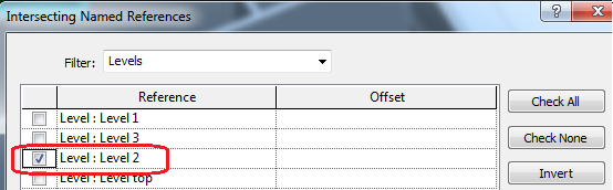
With Revit > Create Parts tool, you can divide elements, which have layers – walls, floors, roofs etc. You can divide them to any direction and any shape. You can sketch division shape or use Division profile family, you can also use levels, reference planes (which must have names), grids to divide elements, separating them with gaps.
Let’s run some basics – I will use solid wall of 200 mm, which goes from level 1 to level 3 as an example:
- In the plan view, hit Create Parts from Modify tab:

- Then you can see additional panel appear with parts;

- Select Divide Parts – you can see Properties and edit tools windows changed. Use Edit Sketch as an option to divide wall vertically;

- Make some vertical lines where you want to divide your panel;

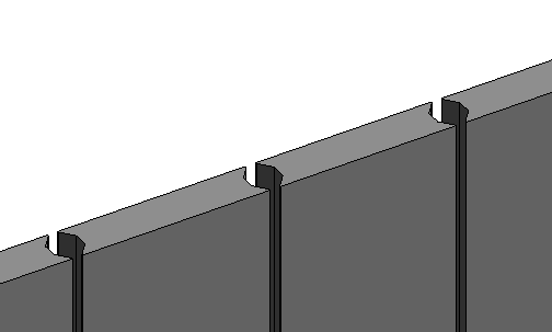
- from properties window, Division profile (it’s a family, you can create on your own) choose Tapered Notch, enter 50 as a gap, set Edge Match as mirrored and click green finish button. You can see the division view as it will be created;

- hit green finish tick marks again to finish your first division operation. The result is, as it is shown below – separate elements – Parts where created and linked to a wall. If you modify a wall – parts will be affected, watch out;

- Now you see both elements’– I mean wall and divided elements – Parts. To control visibility, you can select properties, in the view under Parts visibility – show both, original or parts, so it is easy to control, then you need to switch between final view and the visibility you need during work progress.

Now you’ll have your wall divided into separate panels vertically and horizontally.

What I don’t like here is that gaps are just gaps, but I want them to be – grout, that fills gaps between walls, because I want to include them in schedules etc. So, instead of using profiles to split, I’ll do it in another way. After you select Divide Parts > Edit Sketch, just draw contour of your gap and copy it as many times as you need:

Finish division, and now you can see, that it is possible to select this gap as a separate element and assign different material, if you want to:

You can see pictures below of first (using profile family) and second (sketching parts division) methods for your consideration:

So these were few basics using simple panels. Let’s go to sandwich panels. Maybe you’ll have a panel that has solid inside part, insulation and solid external part. In that case, you just make divisions just like previously, change material for inner part to insulation and you have your panel.

But, what if you want to create a panel that would have beams at the top and bottom, columns on the edges and thicker insulation in the middle? You would have to make at least three division operations and then merge some parts back together again. This is possible and might be useful, but I can do it in other way, again. I can divide panels vertically and then, I insert wall based family with parameters to control its dimensions of extruded solid of rigid insulation and voids to cut my parts after I insert it in the right place. You can see generic family for insulation below:

Anyway, by using Divide Parts and other commands, you can create any shape of precast wall.
After you finish your modeling, you can insert hosted details, area, fabric reinforcement, sets of rebars, create schedules etc. For detailed drawings, if you have just plain Revit without any add-ons, you can use assemblies’ command and create your shop drawings manually, or look for solutions ( for example, Smart Assemblies) that do it automatically (NOTE: you can not include fabric reinforcement in assemblies in current version of Revit 2015).
As with any new command or tool, we try to get it work as we want, it requires some time and skill developed through testing and failure, but I wish you have the patience and succeed already with such models and drawings that are presented below:


This was prepared based on my experience and Revit Structure 2015 possibilities, as I see it. It does not cover all possibilities of Parts tool, so feel free to explore. Hope you’ll find it useful, and encounter less headaches in the future modeling.


