The advent of 3D design and BIM put a new spin on MEP coordination: resolving clashes between elements in a model instead of lines in a drawing.
While MEP engineers working in 2D have to imagine piping or ductwork in their heads while making drawings that then need to be checked for viability by the structural designer or perhaps even on-site by the builder, architects, structural and MEP engineers working in 3D know in advance exactly where MEP elements will be placed during the construction phase, enabling them to create precise models and schedules.
Nonetheless, MEP runs still need to be checked to ensure structural integrity and constructability, and that’s a very time-consuming procedure requiring a lot of attention to produce the desired result, error-free.

Increase productivity
Fortunately, there is a way to dramatically increase productivity in this area. Agacad Cut Opening software for Revit not only inserts openings in your projects where MEP elements intersect structural elements but also facilitates coordination between different disciplines and engineers working on the same project.
When openings are created, each has its own parameters to mark whether it is acceptable or not, and, with the opening control window, you can check the parameters of every single opening in your project that was inserted with our Cut Opening add-in.
What’s more, the control window allows you to create a dynamic section box that will move the section box in your 3D view directly to the opening selected in the table, making it easier to locate and check openings requiring review.
In addition to the features above, the opening families we provide with Cut Opening are available for any user modifications. It’s possible to add things such as sleeves or collars to their geometry, add parameters, and change their representation according to company needs or country codes. We encourage users to take full advantage of the flexibility that Cut Opening brings.
In this post, I’d like to show just one of the possible ways to make openings change color in 2D views to indicate whether they have been Approved, Declined, or Not Yet Reviewed. At first glance, it seems pretty simple to achieve since filters could be used in views that would react to an opening’s Approved and Declined parameters and color it accordingly. But we want a more universal solution, so we’re actually going to modify the opening families themselves.
It’s quite an involved workflow, and I’ll go through it step-by-step below so that you can modify families on your own if you want.

For your convenience, the opening families that I modified during the process of writing this blog post are included as a free download (at bottom). Hopefully you’ll find ways to implement them in your everyday work with Cut Opening to further enhance model coordination.
Setting the stage
Goal:
To modify the graphical representation of an Opening family. Specifically, we want an opening to be green if Approved, red if Declined, and black if neither Approved nor Declined.
How:
If you’ve ever opened our Opening families, you know that they’re face-based void elements that cut their host’s geometry. Associated with each element are some Detail Items, such as Opening Lines, which represent the Opening borders, and Opening Region families, which represent the Opening from the section or plan views. We’re going to change the Opening Region colors, as it has a greater effect on the overall look of the Opening family.
To do that, we have two existing Yes/No (Approved/Declined) instance parameters and we need to make them control the coloring. Since in Revit there’s no direct way to change the material or color of a family depending on its parameter, we’ll need to create two additional Filled Regions of two different colors and then control their visibility via the parameters associated with the Approved/Declined parameters in the Opening family.
Application:
The workflow below can be applied to both Void Openings – used in structural or architectural models – and Solid Openings – used in MEP models where it’s impossible to cut the geometry of a linked file. In this example, we’ll modify a Round Void Opening family.


OK, let’s do this!
Workflow
1. Open an Opening family for editing.
2. Choose to edit the Detail Item family named ‘Opening Region – Front/Side’.

There you’ll find some Filled Regions controlled by reference planes and reference lines. The next task is to create additional Filled Regions controlled by the same reference lines since all the needed rules are already created for those in family parameters. The only difference will be that the new regions will have different coloring.
Here you can see the Filled Region from the left side is set to ‘hidden’ to show the reference lines:

3. Select the ‘Filled Region’ command in the ‘Create’ tab to create a new Filled Region.

4. After the shape has been created, lock every edge of the new region to existing reference lines.

You’ll need to repeat this procedure (Steps 3 & 4) from both sides. Overall you need three overlapping regions. After this is done, flex the freshly created regions by changing the size and angle parameters of the family. If anything breaks, please check if new Filled Region lines are actually locked to reference lines and not something else. If everything’s good, onward!
5. Now that those Filled Regions have been created, change the color of each region by creating new Filled Region family types that will have the specific coloring you want, in this case red and green. By default there will already be some types created. Add or modify two of those by changing their names and colors.

 |  |  |
All that’s left to do at this point inside the Detail Item family is to create Yes/No type parameters which would control the visibility of the regions. Normally, it would be enough to create two Yes/No parameters to trigger one region or another, but we have two additional conditions in our case, namely:
Condition 1 – The family already has one parameter – named ‘Region Visible’ – that controls its visibility. It’s a Type parameter that turns visibility OFF if certain geometric conditions are not met. We’ll need to incorporate it into our work.
Condition 2 – The Yes/No parameters from this opening family need to be associated with the Approved/Declined parameters in the Opening family.
6. So we will need to create a bit more elaborate control scheme.
| If Opening is… | and Region Visible is… | THEN… |
| Approved | True | green Filled Region appears, and all the rest should not be visible. |
| Declined | True | red Filled Region appears, and all the rest should not be visible. |
| neither Approved nor Declined | True | black Filled Region appears, and all the rest should not be visible. |
| Approved, Declined, or neither | False | the Filled Regions will not be visible. |
For that we will need 5 new yes/no parameters. Name two of them Approved and Declined (that will make it easier to associate them with parameters from the Opening family). Name the other three Standard, Approved Visible, and Declined Visible. These parameters will connect the already-existing ‘Region Visible’ parameter to our Approved/Declined parameters.


To achieve that we’ll use AND, NOT, and OR logical operators:
| Approved Visible = AND (Approved, Region Visible) | Value is true if both conditions are met. With any other conditions, it will be false. |
| Declined Visible = AND (Declined, Region Visible) | Value is true if both conditions are met. With any other conditions, it will be false. |
| Standard = AND (NOT (OR (Approved, Declined)), Region Visible) | Value is true if both ‘Approved’ and ‘Declined’ parameters are false and ‘Region Visible’ is true. |

7. Associate the calculated parameters with the ‘Visible’ parameter of the Filled Regions. Repeat this procedure for each Filled Region that was created in previous steps.

8. Just to make sure everything works, flex the family again by changing its sizing or angles and by turning the Approved/Declined parameters ON and OFF. If everything works, load the family back into the Opening family.
9. This step is necessary due to the specifics of the given Opening family. The name of the freshly loaded opening region differs from the one used in the family, so even though we’ve loaded a modified type, we still need to exchange the original one for the modified. Select Opening Region in the family, and change it out with the newly loaded type using the Properties window.

10. Associate parameters from the Opening family with the parameters from the Filled Region family. This only needs to be done for the Approved/Declined parameters.

Your modified Opening family is now ready to use!
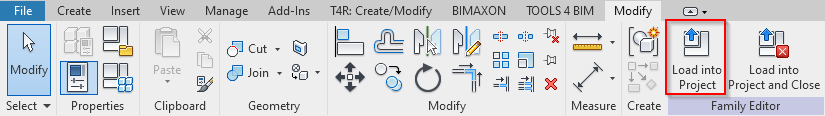
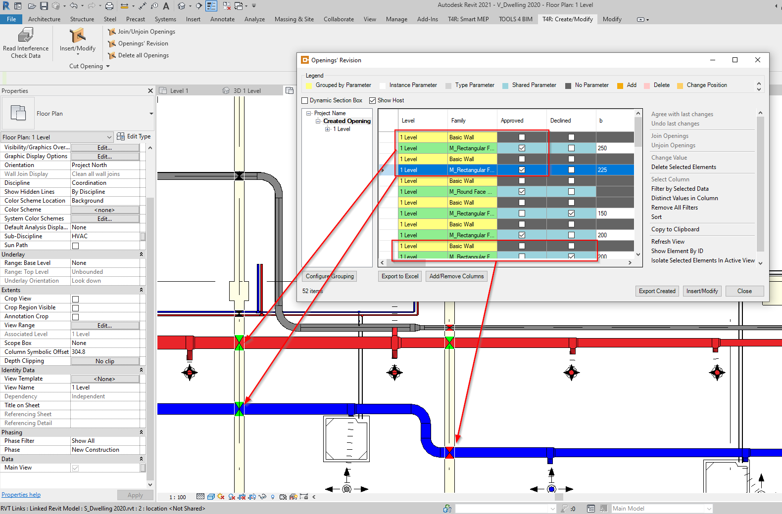
Load modified Opening family into project
Let’s load it into a project and see how it works. If you’re using Cut Opening, it’s possible to click on the ‘Opening Revision’ command and see the Approved/Declined parameters of all openings that have been inserted. But now not only do we have that information – we have the graphical representation as well:
Free downloads
Here are the original Openings that I’ve modified to turn green, red, and black depending on status using the above workflow. Feel free to download and modify them further!
| Metric Opening Families 2021 | Imperial Opening Families 2021 |
| Metric Opening Families 2020 | Imperial Opening Families 2020 |
Add these Opening families to the Cut Opening family library located in the following folder: C:UsersUserNameAppDataRoamingTOOLS 4 BIM2020Cut Opening20.8.10701.0Cut OpeningLibrariesMetric
The values in yellow may obviously vary: user name on your compute, the Revit version on which Cut Opening is running, and the installation version of Cut Opening. The Cut Opening version will change as new updates are released, so we recommend keeping your modified Openings in some other folder as a backup to avoid their getting overwritten.