 Probably the most HVAC designers’ dream is faster and more convenient ventilation system design. Already Autodesk® Revit® accelerates the work flow but not in all design stages. We offer you a simple tool that will help you quickly choose the appropriate item for ventilation system from your library.
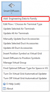
After establishment of element geometry it remains only to add necessary engineering information for this. Here our application Smart Diffusers for Autodesk Revit can be useful. Extension allows Revit MEP users to add unlimited number of engineering parametric equations into the MEP families. That defines relations between main HVAC parameters like Pressure Drop, Sound Power Level, Air Flow, Velocity, Throw, Duct Diameter, Free Area and other.
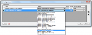
The Smart Diffusers feature Configuration allows you to select configuration modes with described relations and priorities. Configuration name can by editable. Working with Smart Diffusers API Revit user can create new configurations, duplicate or delete them. Relations are created between different parameters like Pressure, Air Flow, Velocity, Throw, Flow Density, Type Dimension, Type Area and more.
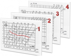
Priority is used for parameter’s calculation in predefined way. Calculation results go from one graph to another by priority – step by step from graph with the highest priority to graphs with lower priorities.
To import information from images to catalogues you just have to take a snapshot in a .pdf file or other file format. Load Image – loads image with a chart from a file that will appear in Chart Image Window. Paste – image can be pasted from the clipboard with original dimensions. Images formats can be as following: JPG, JPEG, GIF, BMP, and PNG.
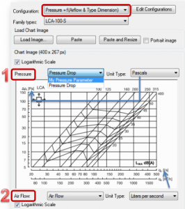
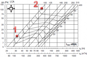
Look closely at the image above. 1st position – value depends on the configuration and goes for Y axis in the chart. In this example, Configuration is “Pressure = f(Airflow & Type Dimension)”. The 1st position is Pressure. For the “Pressure” user has to select the family instance parameter with “Pressure” type. This parameter will be used in calculation.
2nd position – value depends on the configuration and goes for X axis in the chart. In the upper example Configuration is “Pressure = f(Airflow & Type Dimension)”. The 2st position is Air Flow. For the “Air Flow” user has to select the family instance parameter with “Air Flow” type. This parameter will be used in calculation.
Unit Type feature selects unit types for Y and X axes. Unit types must be the same as in the chart (not in the family or project).
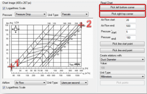
Pick left bottom corner selects a point in the left bottom corner of a graph. See point indicated as “1”. Pick right top corner selects a point in the right top corner of a graph. See point indicated as “2”.
Air Flow start – value depends on the configuration and value for minimum rate on X axis of a chart. Air flow is the maximum rate on X axis of the chart. Pressure start and Pressure end go in the same way only on the Y axis.
Pick line start point allows you to pick a point in the beginning of the line for corresponding type. Pick line end point enables to pick a point at the end of the line for corresponding type.
Now all necessary information is loaded from a catalogue to your own diffuser family. This information can be used for selection of air terminals in spaces. Afterwards information will be included in your pressure drop calculations.
I suggest you to try BIM application Smart Diffusers for Autodesk Revit and improve your productivity working with diffusers and other Revit® MEP elements!

