Parking garages can be built from a variety of materials – cast-in-place, precast concrete, steel framing with concrete, even wood. Perhaps most often seen as stand-alone buildings, they are frequently incorporated into a larger structure, concealed below ground level or several floors above ground. Architecturally speaking they can range from simple to highly unique, boasting tailor-made façades. Functionally most are quite plain though they may be outfitted with complex automatic parking systems.
At any rate, we need them. A lot. That’s why they’re being built all over the place. Here in Vilnius, Lithuania, car parks are gradually relieving the lack of parking spaces, an all-too-common problem affecting cities worldwide. Underground ones are ideal in the city center here for preserving views of the city’s splendid architecture. Although every situation is different, precast concrete is probably the best choice for your typical, economical, functional parking structure due to its relatively simple design and fast construction timetable that’s less affected by weather conditions. Plus architectural ideas can easily be implemented in façade wall panels.
The AEC industry has been undergoing the transition from 2D digital drafting to 3D informational modeling, data management, sharing, linking between people and software platforms.
In four words, building information modelling/management.
In a word, BIM.
 Image courtesy of CKR Engineers
If we look at the case of an independent, standalone parking garage building, most of it is structural. A typical one has simple architecture, and there’s hardly any MEP or other parts of the project to deal with. So in this article, I want to review the design workflow and available tools that make the process efficient in structural BIM models, particularly as regards modeling and documentation.
The design process for structural engineers (let’s put lead engineers, modelers, technicians, etc. under one name) is to get information from the architect, like plans and elevations, and start building up the model based on standard building codes, data from structural analysis, previous experience, common building practices in your country, input from the manufacturer for the project, etc. Skipping over the inevitable complexities that arise in building design, different software, communication, and data exchange, you have the 3D model and can get documentation out of it. This is the part where AGACAD has a wealth of experience and has helped lots of precast customers work more efficiently in BIM.
One main idea of BIM modeling is to have all the necessary information at your fingertips throughout a building’s lifecycle. That’s why we model elements and give them properties (material, mark, manufacturer, fire resistance class, etc.) That way when someone, be it during construction or years down the road, selects a physical element, he can see textual information about it. Also, a 3D model eliminates mistakes easily made in 2D. For example, a section view might not correspond to the plan view, or the number of elements might be outdated. That’s why it’s crucial that BIM models are modeled accurately, so that we can utilize them to their full potential.

Your typical 3-story parking garage project modeled in Revit will consist of quite a lot of elements. How many? Let’s take a 55m x 85m (180’ x 285’) plan and work out some rough estimates, starting with the foundations, columns, beams, slabs, walls and then moving to various connectors, cut outs, and reinforcement. If you’re trying to reach LOD350 (real geometry + connections), you’re going to have several hundred precast elements and more than 15,000 connection and cutout elements, each of which must be accurately placed and modeled with its own geometry, physical properties, and functional purpose.
Columns and walls will transfer all the loads to the foundations, but their total number will be less than the slabs, which are usually double tees because of long spans. Other types of slabs, like hollow core and solid slabs, could also be used in certain areas, depending on the parking building plan. In the image of my Revit model above, there are over 200 DT slabs.

Image courtesy of Schaefer, Inc.
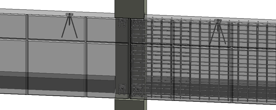
Since precast elements are produced in a factory, all of them have to be transported to the site and then put together. This calls for a huge number of connection hardware, 15,000+ for your typical garage. In a Revit model these will be Families (blocks of solids and voids) of Structural Connection and Generic model category elements – plates, grout tubes, embedded details, lifting embeds, loose plates to weld on site, cuts, reveals, etc.
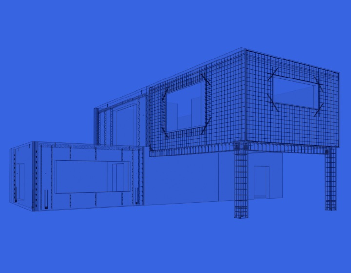
Moving on to rebar, if we want to reach LOD400 and model reinforcement, the number of elements will increase by a factor of 5. This information is needed for drawings, coordination, and export to CAM machines for manufacturers with that capability.
So, the number of elements in a 3D model of a typical parking garage will be in the neighborhood of 70,000 Revit objects, three-quarters of which will be reinforcement, a quarter connections, and <1% actual precast elements. The numbers of course will vary for every design, but they’re indicative of how much modeling work has to be done. Thankfully most of it can be automated.
After modelling of course there’s documentation. Although drawing styles and standards vary by country and manufacturer, for each precast element you need anywhere from 1 to 4 sheets. Each sheet in turn has views – elevations and sections, typical details, unique details, production notes, schedules and rebar shapes. If we need, say, 15 views for each element, that means 6,000 views for the whole parking building. Each needing text and dimensions, values filled in schedules, etc.
By now we’ve crossed into the 5-zeroes zone for the number of attributes needing to be documented. The point is, what if we could automate 90% of this work? Even 70% or even 50%? How many repetitive clicks would we avoid?
A LOT. Hours and hours and hours’ worth.
Enter AGACAD’s Precast Concrete BIM software.
Proposed workflow for modeling & documenting precast parking structures in Revit
1. Create building axes, columns, beams, walls, stairs, and floors. Use native Revit commands.

2. Use Floors as a reference boundary to automatically create layout of Structural Framing elements. Use Floor+C tool in Precast Concrete.

*For warped double tees:
a) Create layout of Structural Framing elements using special DT families for auto-warping. These will be used to define the position of corbels, connections plates, etc.
b) Copy warped DT to the same place and make planar by changing one parameter. The flat DT version will be used to create assemblies and shop drawings.

3. Distribute connection details. Use Smart Connections tool in Precast Concrete.

*For warped double tees:
a) Create connections on walls and columns based on position of warped DT.
b) Create all connections and cutouts for flat DT elements.

4. Create reinforcement. Use native Revit plus Wall Reinforcement and Beam Reinforcement tools in Precast Concrete.


5. Renumber elements. Use Sort Mark tool in Precast Concrete. Assign mark values to different element categories by numbering and sorting rules.

6. Auto-generate shop drawings. Use Smart Assemblies tool in Precast Concrete.


Throughout this whole process, the elements manipulated by AGACAD’s Precast Concrete are native Revit elements: Revit Families, Dimensions, Text, Title blocks, Schedules, Legends, Sections, Elevations, Plans, Details, etc. That means you can use families, styles, templates, and types of elements that you already have.


